Yano, N. Sato, Akutsu; to follow 20963.
Summary
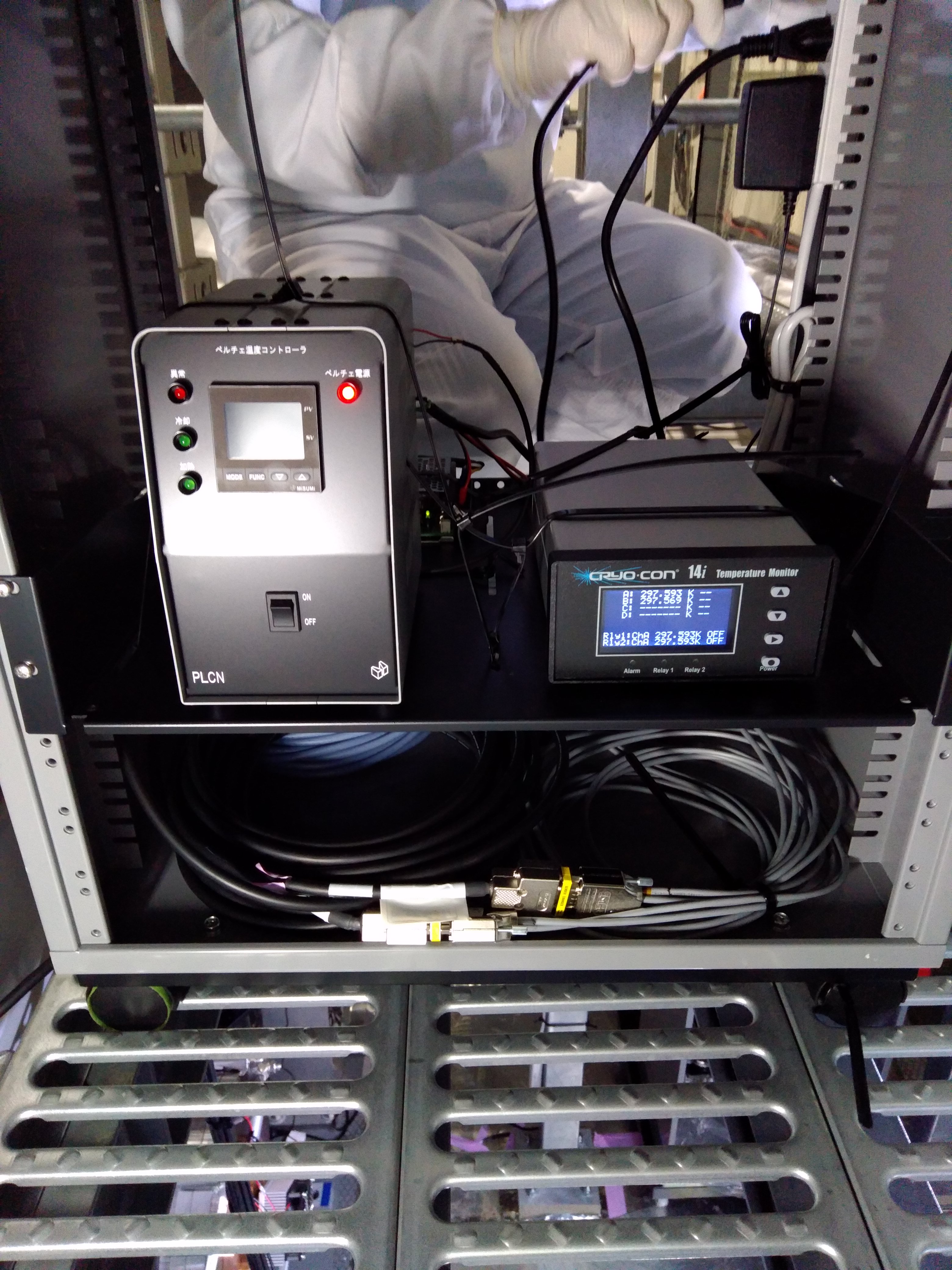
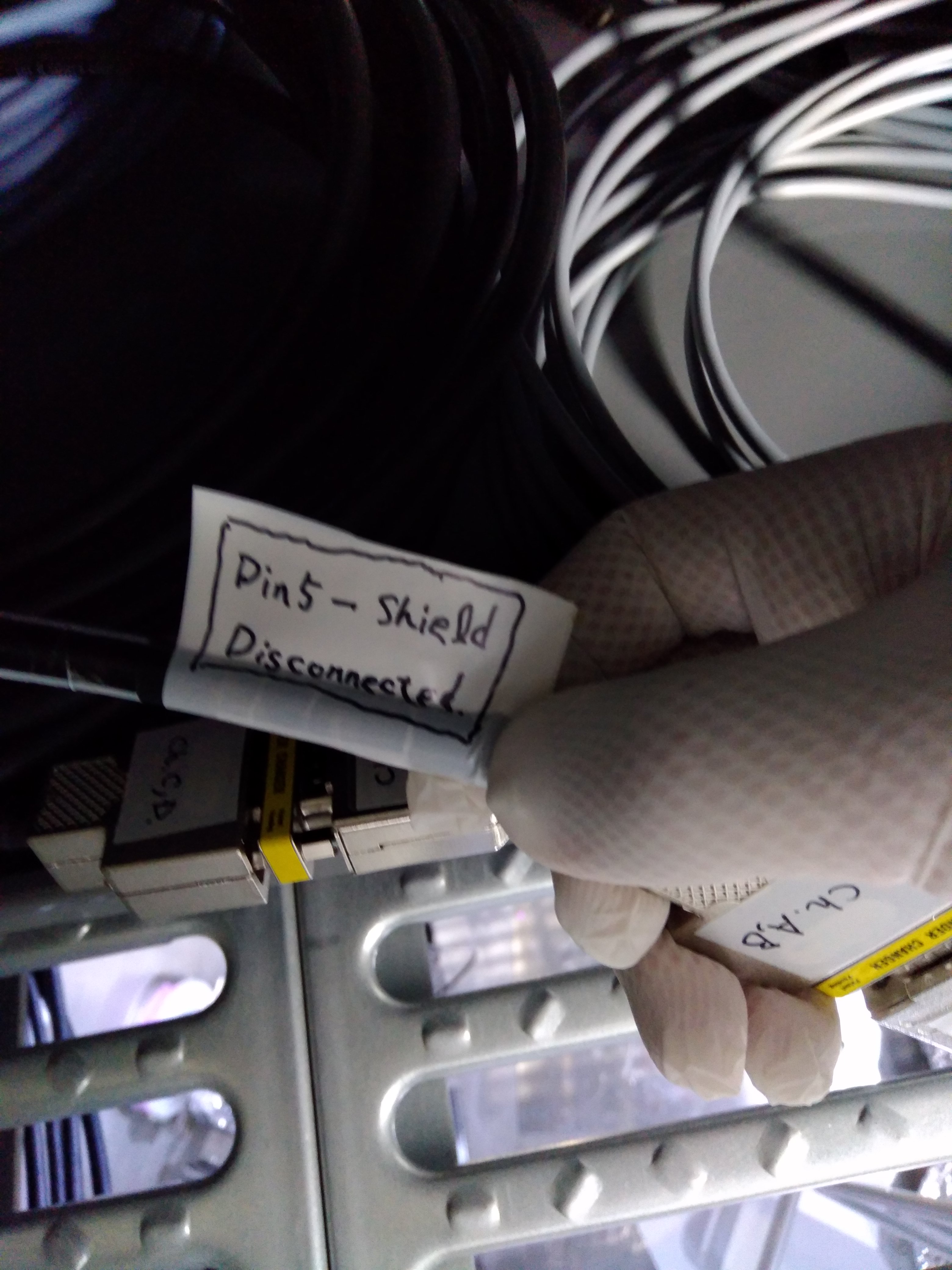
- Checked the connection of the thermometers on the high power beam dumps to the cryocon; Satou-san might be report later.
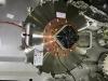
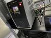
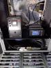
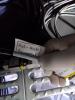
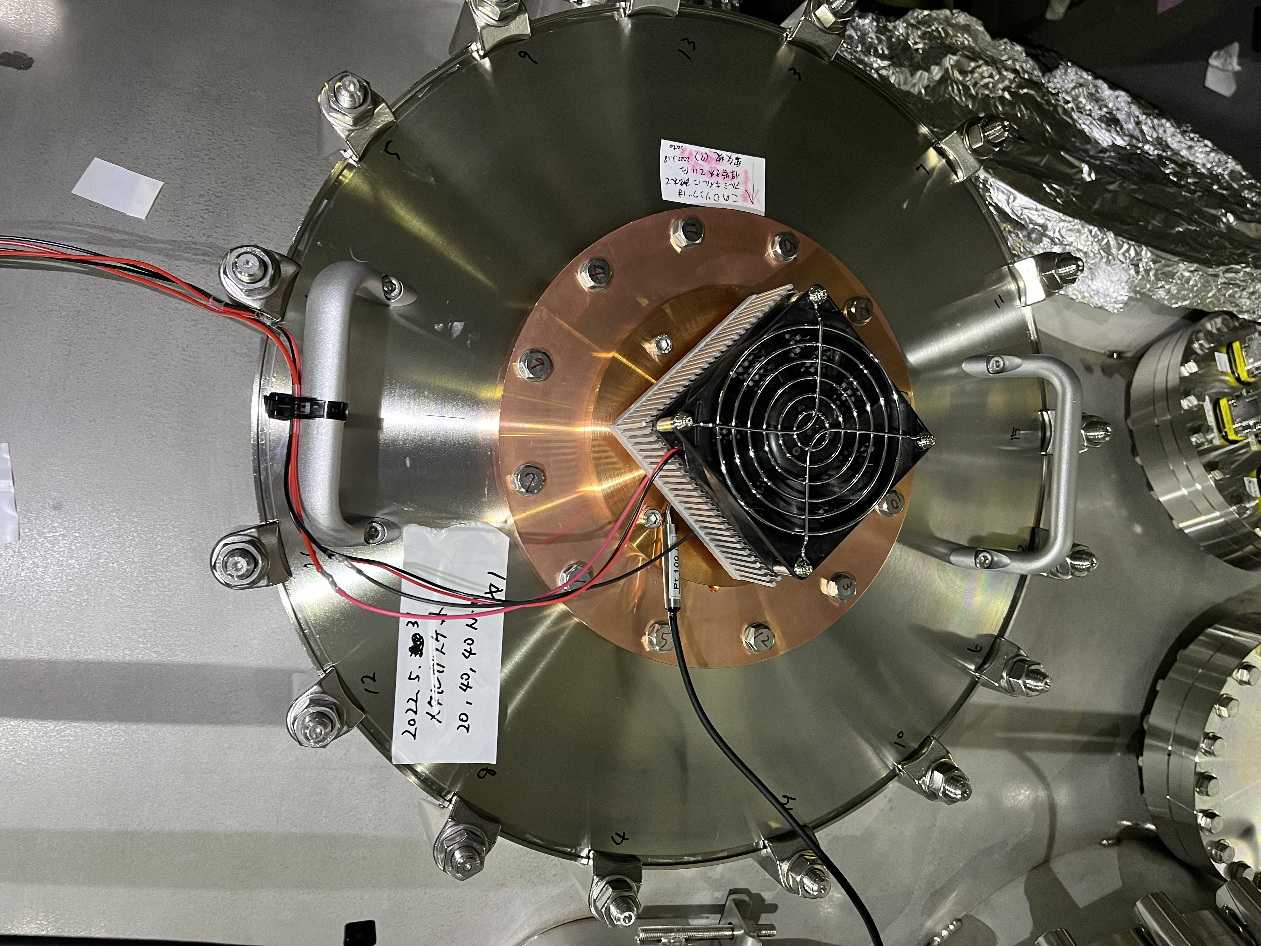
- Installed the Perlier unit onto the Cu flange (Figs. 1 and 2), and connected it with the driver and the power supply, and roughly comfirmed it work. They are all turned off now for safety.
Note
- Not yet fully completed; we'd like to installed an additional thermometer on the top surface of the optical bench in the IFI chamber, and the design will be done in the next week.
- We need to discuss within KAGRA how to manage this system. It does not need to keep being turned on unless the invac high-power beam dump would be illuminated by the reflection beam from PRM, especially in high power. It equips a didicated thermometer, and a PID controller, but the discussion point here would be what should be the objective value of the controlled temperature; and maybe also some paramters for the PID.
- The Peltier unit has a mechanical heat sink and a fan; the fan might be a noise source when it would run, but reminding that this beam dump will be illuminated only PRM would be (intentionally) mis-aligned, meaning the interfeometer would not be in operation with the highest sensitivity, so we may not need to care much such things.