Reports 1-1 of 1 Clear search Modify search
MIF (ASC)
hirose.chiaki - 8:32 Thursday 02 June 2022 (20983) Print this report
TF measurement of RFQPD for WFS on the REFL

With K.Tanaka

I have been measuring the spectrum, TF and phasing of the RFQPD for WFS on the REFL surface plate since yesterday.
We will do it again tomorrow.
I referred to klog#16774.
RFQPD for WFS at REFL is for demodulation at 17 MHz, 45 M Hz.
What I need to measure is QPD{1,2}_{17Hz,45Hz}.

TF measurement of RFQPD

TF measurement of RFQPD
We measured the transfer function of each segment of RFQPD.
Two methods were used to measure it.
I applied an excitation signal from Moku Lab to the TEST of RFQPD and measured the transfer function of each segment.
The excitation signal was applied from Moku Lab to the AM laser and then from the AM laser to the RFQPD, and the transfer function of each segment was measured.

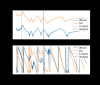
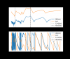
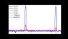
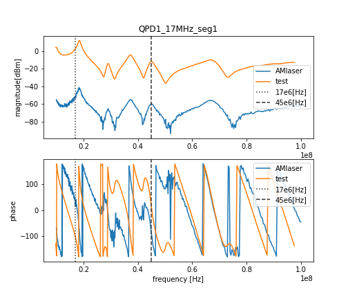
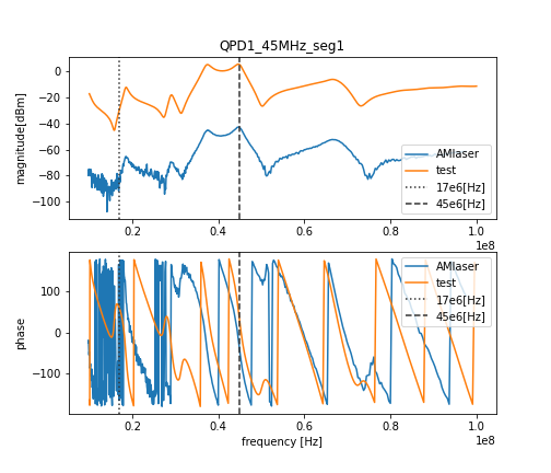
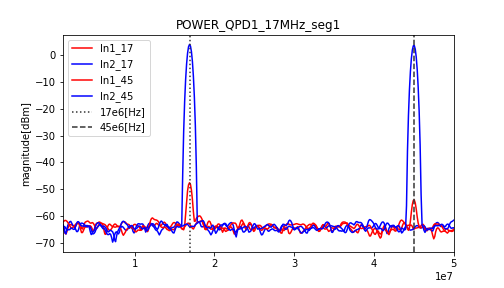
The figure shows the transfer function of the test and AM laser at 17 MHz and 45 MHz for QPD1 and the
power spectrum when differenced at 17Hz.
Figure 1 (transfer function results at 17Hz) shows that at frequency 17Hz it is not peaky, and at frequency 45Hz magnitude lower than 17Hz but does not appear to be abyss.

Ideally, the waveform would be peak at 17Hz and abyss at 45Hz. I need to check if QPD1 is frequency tuned.

I measured the transfer function of QPD1 and the power spectrum.
QPD2 measurements are on the way. I will summarize the method and results later.

Images attached to this report
Comments to this report:
hirose.chiaki - 23:35 Sunday 05 June 2022 (21025) Print this report

With K.Tanaka and Tamaki

We performed transfer function measurements and phasing on the QPD from Monday to Thursday last week.
We summarised their setup and results.

TF measurement of RFQPD

The degrees of freedom are WFS_RFQPD{1,2}_seg{1,2,3,4}.
Measurements of the transfer function of the RF QPD were superimposed when using the AM laser and when using the test.
TF for all degrees of freedom are different in magnitude, but the waveforms are almost the same.
The QPD1 is discussed in 20983. However, due to the strong low-pass filtering in the digital system, the 45 MHz information disappears, so it is not necessary to consider it.
With QPD 2, it is peak at the frequency we want to see and not at the other frequency. So there is no problem with signal acquisition.

RFQPD phasing

In the 17 MHz band, the frequency of the function generator was set based on 16.873935 MHz, plus the frequency for the beat.
In the 45 MHz band, the frequency of the function generator was set based on 44.997157 MHz, plus the frequency for beats.
When the beat signal was viewed in the power spectrum, power was seen at the frequency added to the reference frequency. The phase difference of segments 2-4 with respect to segment 1 was measured and set on the MEDM screen.
The result was a phase difference of 1 or less.

Non-image files attached to this comment
Search Help
×

Warning

×