Kokeyama, Ushiba, Yasui, Tomaru, Yokozawa, Akutsu; Follow up of 19345. (On 2022 Jan 5)
Abstract
We tried to overlap the IR beam onto the GreenX by tweaking IMMT2 and PR2, and that has been mostly done. Now (1) the IR and GreenX seem on the central ponts of PR2 and PR3; (2) The IR beam spot appears on the POP S-pol camera, and this fact also means that the GreenX input optical axis and IR_PR2_TRANS_BACKWARD are overlapped well; (3) Besides, the IR beam also returns at the input port of the IFI without mostly clipped. Note that due to the limited aperture size of the mid-size baffle in front of PR2, it seems that the IR beam aligning would become more difficult than those in the O3GK era, while that means that once the overall optical alignment becomes nicer, the IR beam (and of course GreenX) would not be clipped; a nice tendency.
Details
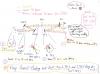
See Fig. 1. In short, our activity today was to repeat or iterate the step A and B shown in the figure, and sometimes checked point C and D. This strategy was constructed according to the basic optical alignment theory "tweak the far-side mirror while looking at the beam spot in front of you", which would be done by everyone on a table-top experiment. With this iteration, our goal is to achieve the followings at once.
- The IR and GreenX spot are simultaneously on the central ponts of PR2 and PR3.
- The GreenX input beam and IR_PR2_TRANS_BACKWARD are overlapped.
- The IR beam returns at the input port of the IFI without clipped. (Note! Here the forward and backward IR beams must not be overlapped here! They should be displaced in a certain amount!!)
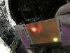
By the way, in this morning, we started with the situation shown in Fig. 2 (at in-between PRM-IMM chambers; the red spot is of IR_FORWARD, and the green spot is of GreenX_BACKWARD (GreenX reflected at PR2 to IMMT2)), and only did step B in Fig. 1. In other words, we only tweaked PR2 to overlap the IR forward and backward beams; or rather, tried to overlap GreenX_BACKWARD and IR_FORWARD, and found the IR beam at the input port of the IFI. But in hindsight, this may have been a misunderstanding; the IR beam would be clipped anywhere (maybe not IFI but the mid-size baffle aperture in front of PR2). In fact, immediately after lunch, we found the IR beam and GreenX spots were displaced on the PR3, while GreenX spot did not move from the center of PR3.
So, we determined to do the iteration already mentioned above; repeated step A and B, and sometimes check the points C and D shown in Fig. 1. After several iterations, we finally achieved the "nice" alignment fulfilling that the items 1, 2, and 3 listed above, mostly. Maybe still a few more iterations would be needed in my personal thought. We will continue the work tomorrow.
Notes and outcomes
- As far as we learned today, GreenX_BACKWARD is not necessarily overlapping on the IR_BACKWARD; it would be better to pay attention more on the IR_BACKWARD beam than that for GreenX_BACKWARD.
- Due to the item 2 above, the IR beam spot appears on the POP S-pol camera. The beam spot shape is not so strange; looks like roundy. So the strange beam spot shape found during O3GK might be just due to clipping in the interferometer but not due to birefringence of some optics (?)
- About point D and item 3, as already noted, the forward and backward IR beams must not be overlapped! The more important check point is to see whether (1) they are displaced and (2) the backward beam is not clipped anywhere (IFI aperture and/or the PR2 mid-size baffle aperture).