[Ikeda, Fabian, Hirata, Yano, Ushiba, with remote help of Akutsu, Aso, Miyoki, Oshino, and rTakahashi]
Abstract:
We checked the current beam GreenX eam position at HR-side mid-size baffle and PR3-side flange on PR2 chamber.
We also measured the PRM-PR2 line at the same places, which is the line connecting PRM center and PR2 center before PR2 problem.
Then, GreenX position at PR3 was also checked.
After checking above things, we moved traverser and adjust PR2 transverse and yaw position with respect to PRM-PR2 line and OpLev QPD center, respectively.
Then, GreenX at PR3 was checked again: which is currently almost center but slightly off to +Y direction.
Detail:
Before moving traverser of PR2, we checked several things: PRM-PR2 line made by markers at the ground and current PRM center, beam ceparation between GreenX from PR2 to PR3 and PRM-PR2 line at HR-side mid-size baffle, and GreenX beam position at PR3.
Figure 1 shows the PR2 target with PRM-PR2 line (green line of laser leveler) and the green marker was slightly shifted to +Y side.
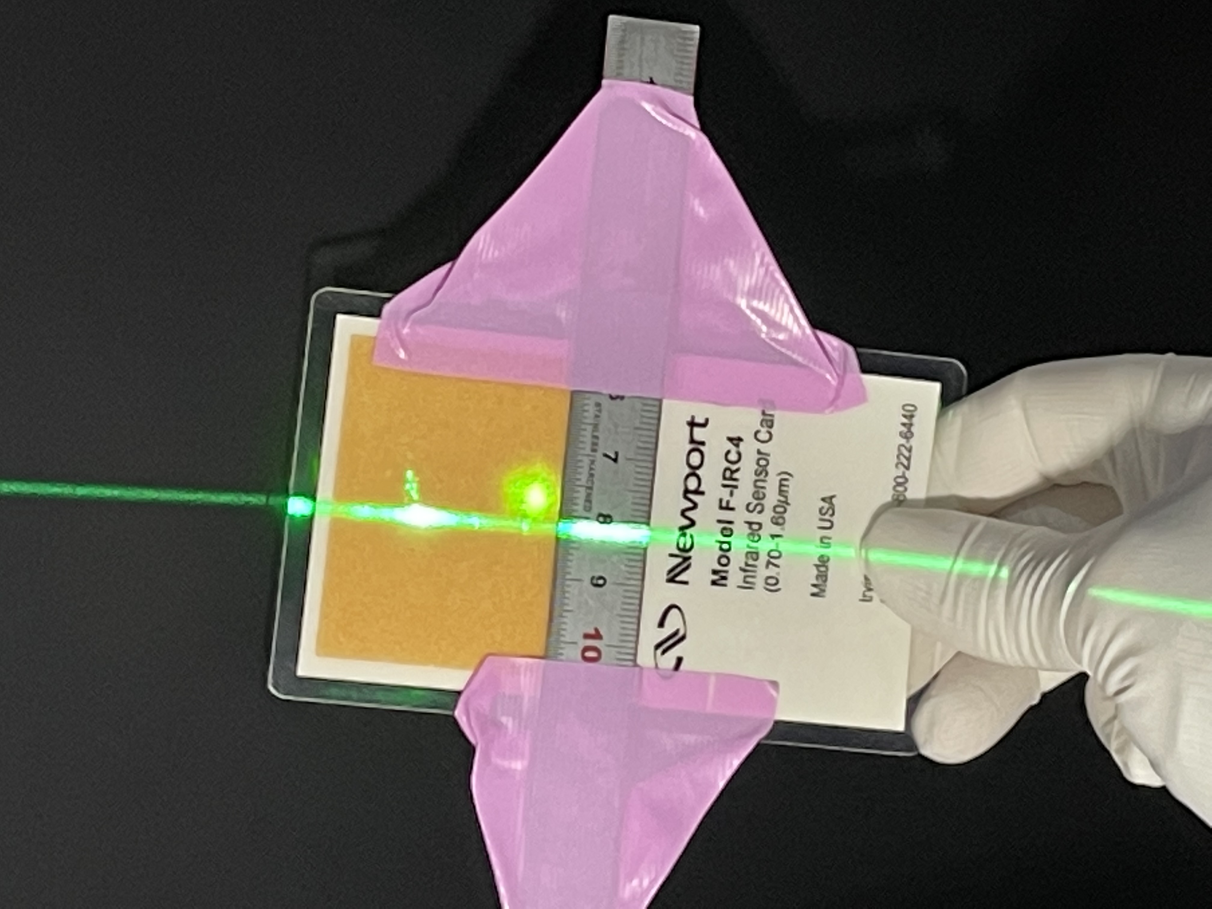
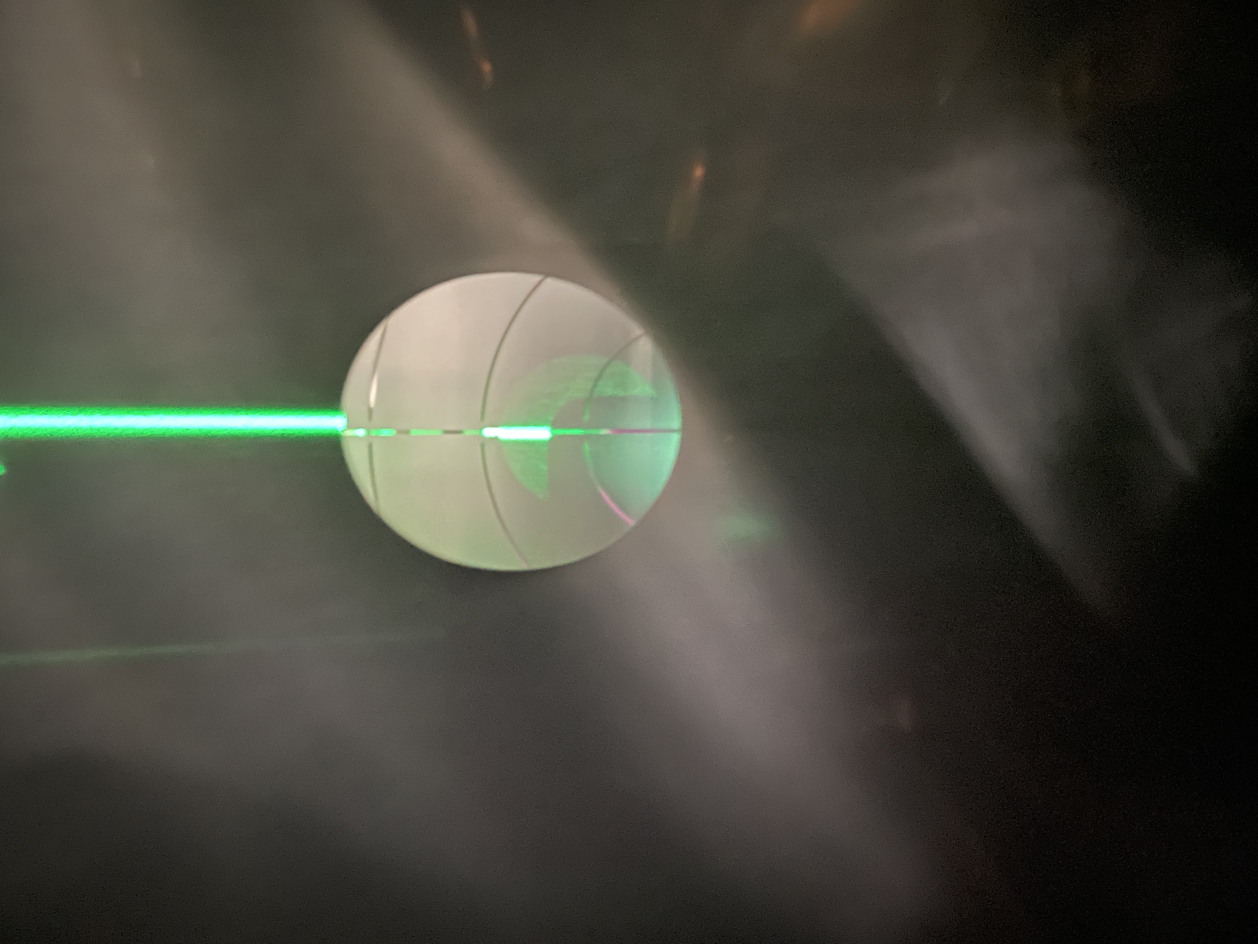
Figure 2 shows the beam ceparation between GreenX from PR2 to PR3 (circular green beam) and the PRM-PR2 line at HR-side mid-size baffle.
Even though it is difficult to say precisely, the beam separation is about 4.5 mm, which should be 6.744 mm according to the document of mid-size baffle (JGW-T2113078).
So, the beam separation has 2.2 mm difference from the design, seems too far.
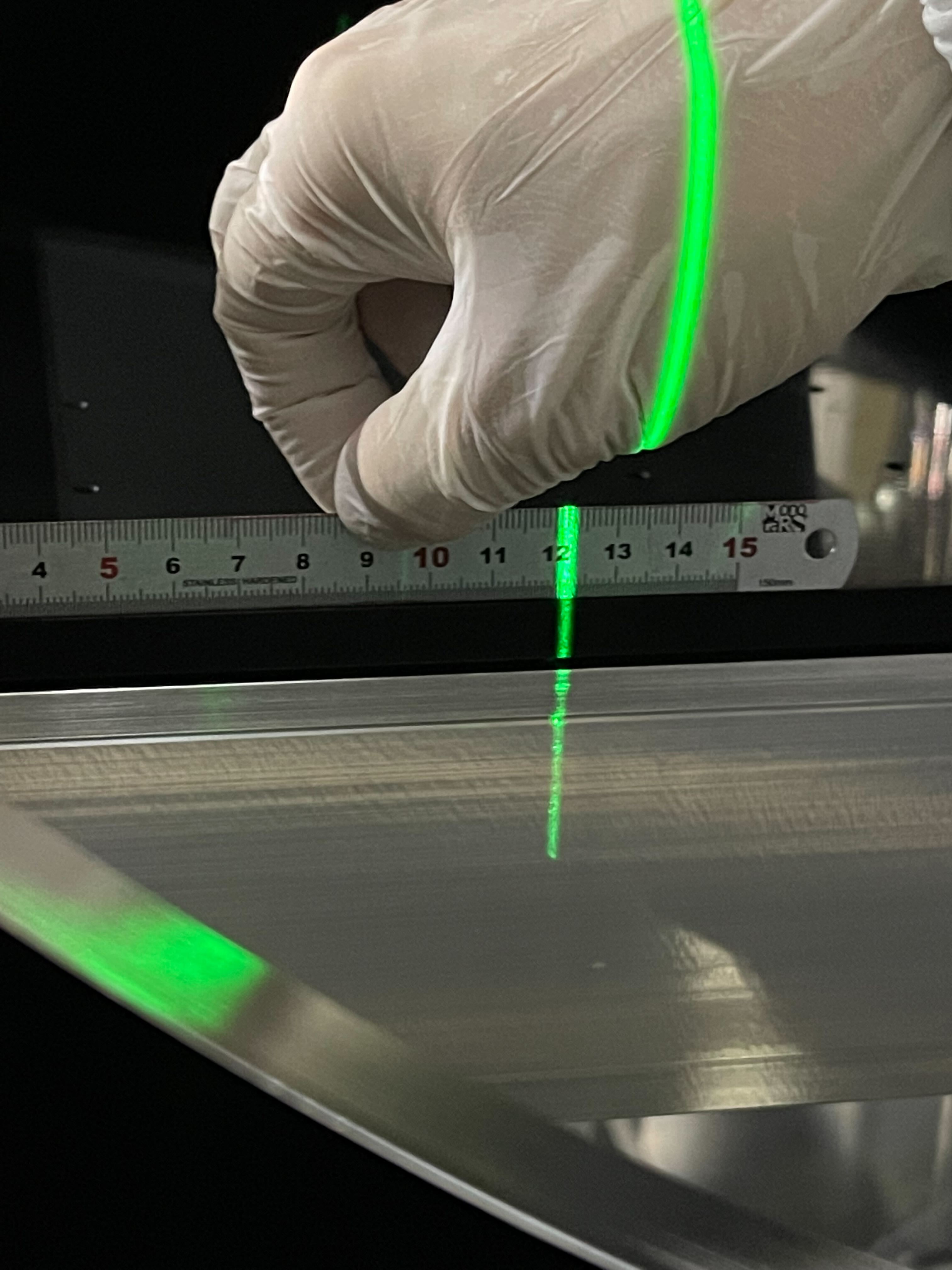
Then, we measured the mid-size baffle position with respect to the PR2-PRM line.
Figure 3 shows the PR2-PRM line with ruler at HR-side mid-size baffle.
The ruler edge (zero point) is touching the flame strauture of the baffle, and PRM-PR2 line is at the position of about 121.8 mm, which should be 119.573 according to the document (JGW-T2113078).
So, the gap between measured value and design value is about 2.2 mm, and current mid-size baffle position is 2.2 mm shifted to +Y direction if we think PRM-PR2 line as a reference.
Note that since the beam separation of GreenX from PR2 to PR3 and PRM-PR2 line is about 2.2 mm far from the design, this 2.2 mm shift is consistent if the baffle is set with respect to the GreenX to PR3.
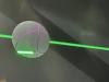
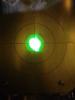
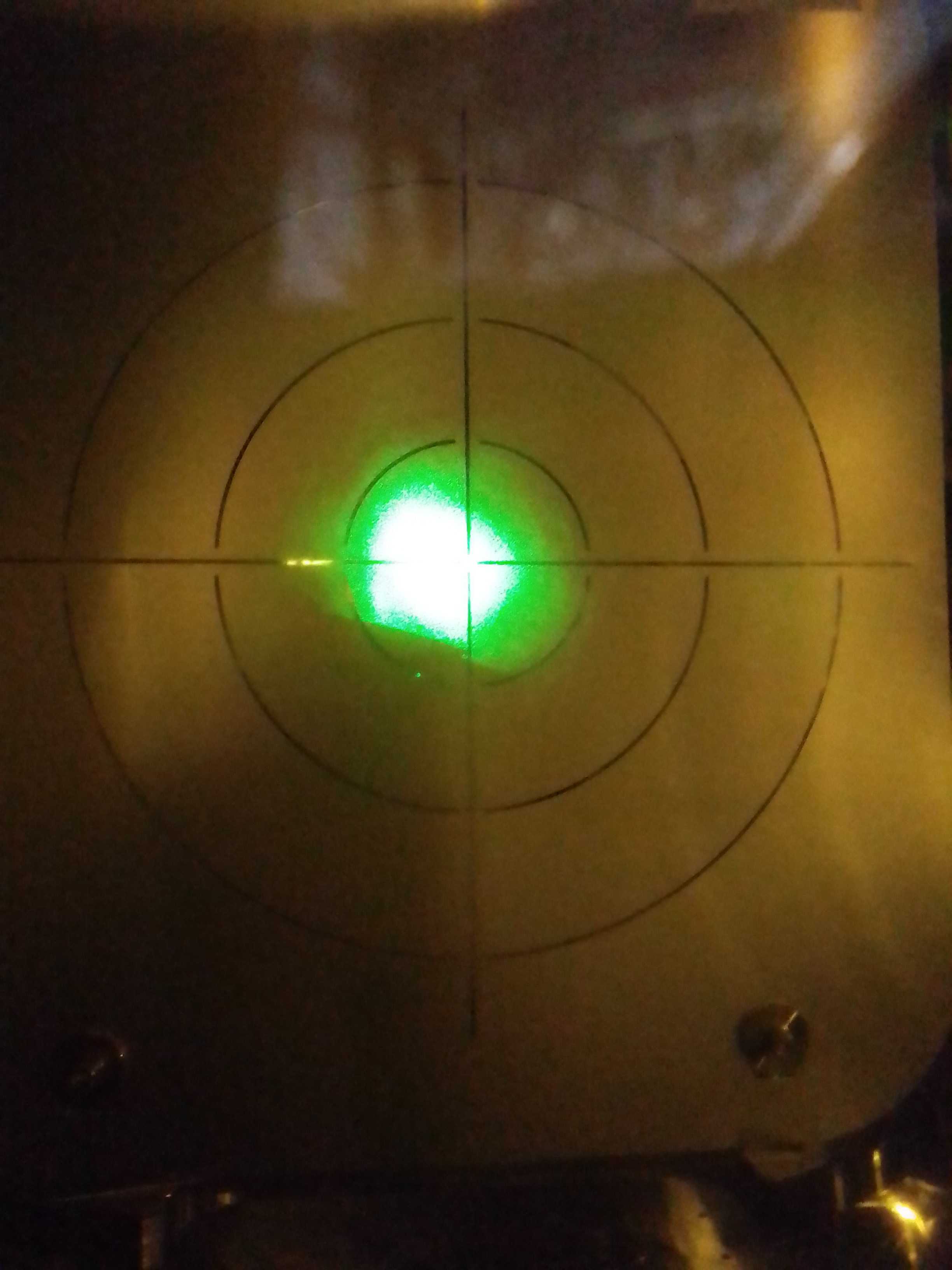
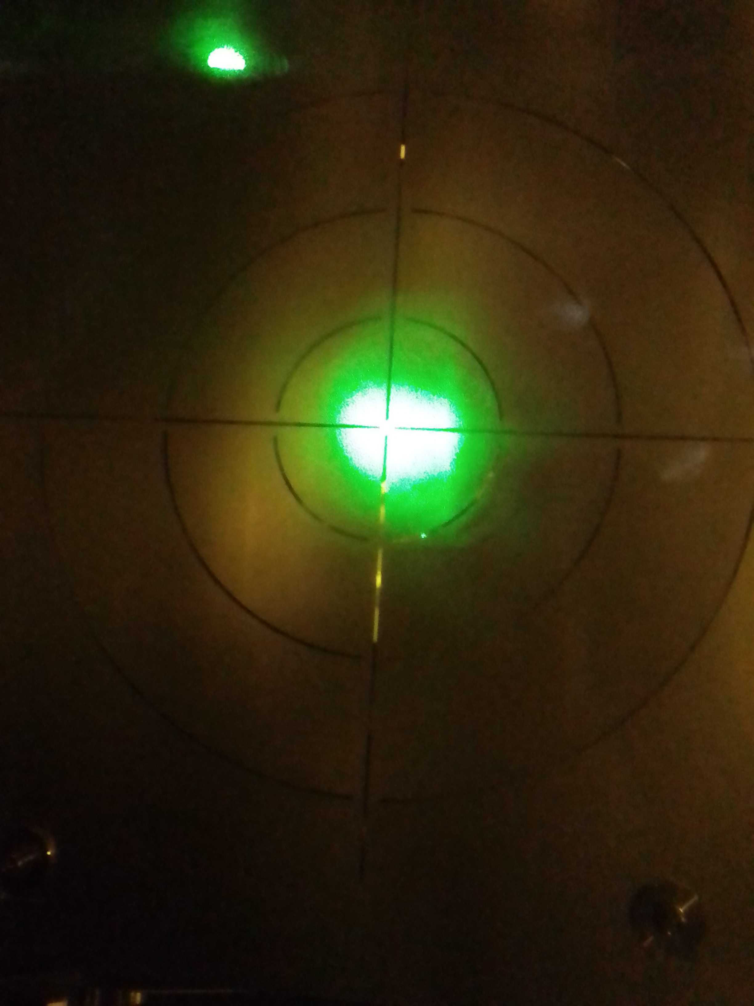
Figure 4 shows the GreenX beam position at PR3.
The beam was shifted -Y direction.
After checking above things, we moved PR2 traverser and adjust the PR2 position to PRM-PR2 line (fig5).
The traverser moved +320 um along X direction and -320 um along Y direction.
Note that above X and Y axes are about 45-degree rotated coordinate from the suspension local coordinate like L and T.
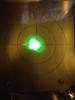
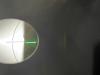
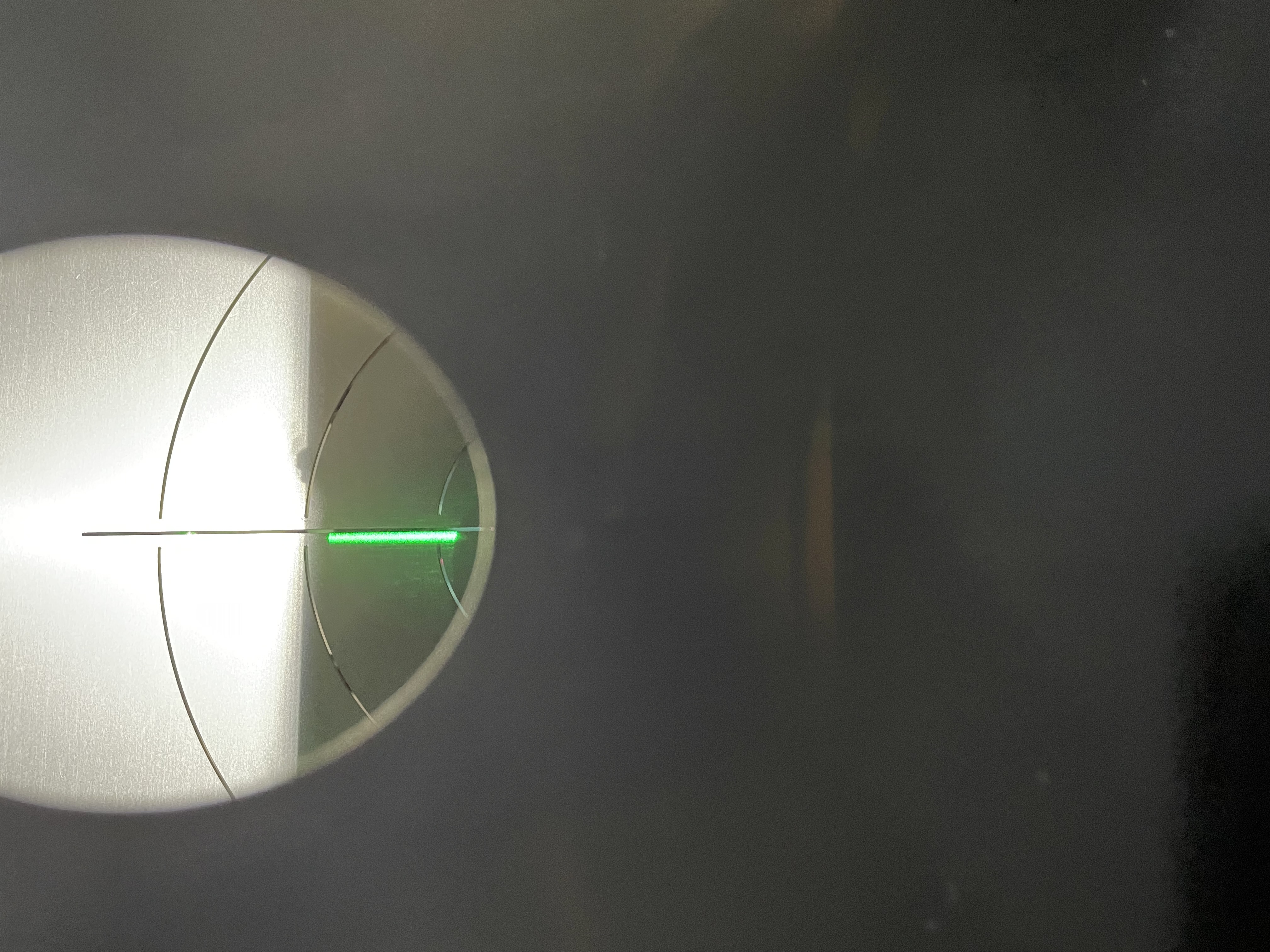
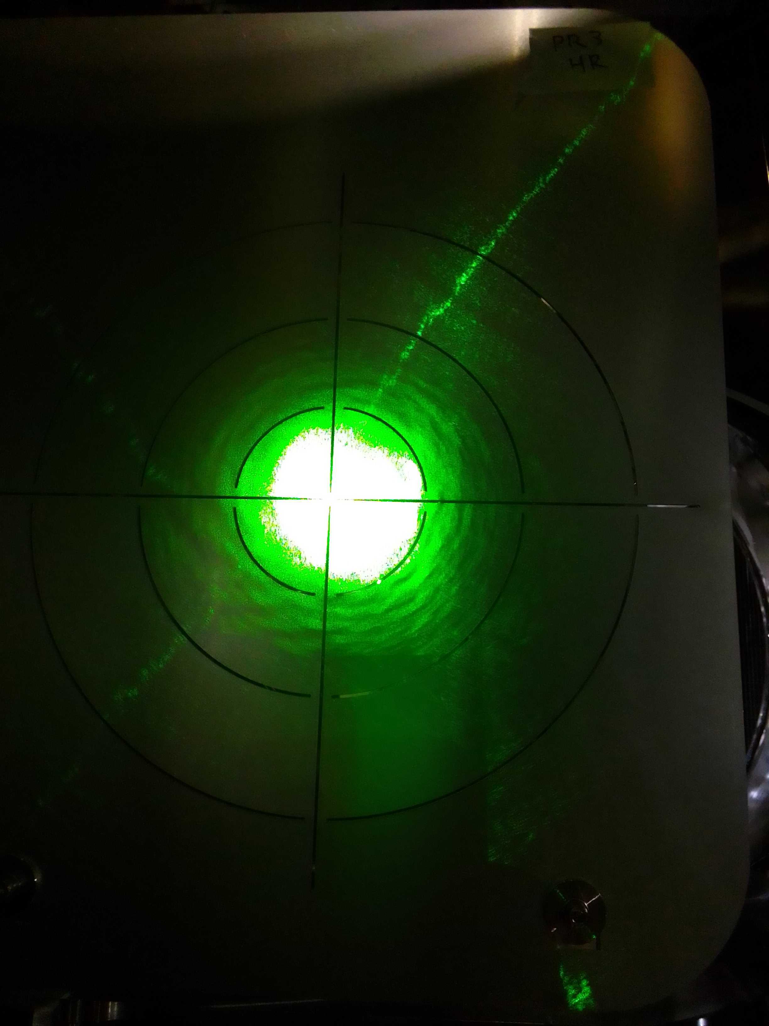
Figure 6 shows the GreenX beam position at PR3 after moving traverser.
The GreenX hit almost center of PR3.
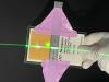
After moving traverser, we measured the beam separation between GreenX to PR3 and PRM-PR2 line at PR3-side flange of PR2 chamber.
During the measurement, we set additional laser marker holizontally at the height of PR2 chamber center (fig7).
We aligned a ruler with red marker to avoid tilting too much and set 370 mm line at the edge of the PR2 flange (fig8).
Figure 9 and 10 show the position of PRM-PR2 line (about 87 mm) and GreenX from PR2 to PR3 (about 76.5 mm), respectively.
So, the beam separation is about 10.5 mm at the flange.
Then, we moved PR2 in pitch and yaw by using Pico motor and traverser, respectively, as the OpLev beam hits the center of QPD.
To align the PR2 traverser was moved an angle of 460 mdeg in yaw.
Note that above movement is -460 mdeg for traverser local coordinate.
On the other hand, I don't know how much Pico moved for centering in pitch.
Since the center of rotation is not at the PR2 target position, PR2 target moves with respect to the PRM-PR2 line during the centering work (fig11).
So, we moved traverser horizontally (+1020 um along X and -1020 um along Y), and align PR2 with respect to PRM-PR2 line (fig12).
Then, we checked GreenX position at PR3 again.
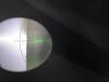
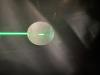
Figure 13 to 16 show the PR3 target with GreenX with several conditions, and GreenX beam seems slightly off to +Y side.
So, we need to check it again after finely adjusting the PR2 angle by using main IR beam.
After that we recovered all the beam duct between PR3 to BS and searched the GreenX beam at X end (klog19290).
Note:
Several related chats were stored at o4_preparation channel on slack.

.jpg)
.jpg)
.jpg)


.jpg)
.jpg)
.jpg)
.jpg)
.jpg)