Reports 1-1 of 1 Clear search Modify search
VIS (BS)
fabian.arellano - 15:58 Wednesday 24 November 2021 (18982) Print this report
Mounting place for the laser displacement sensor.

Summary: in order to calibrate the F1 LVDT, we need to mount an additional sensor in the suspension. Today I identified a good place to mount it.

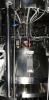
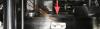
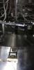
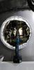
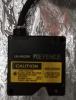
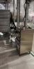
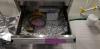
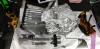
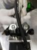
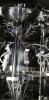
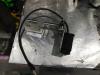
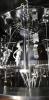
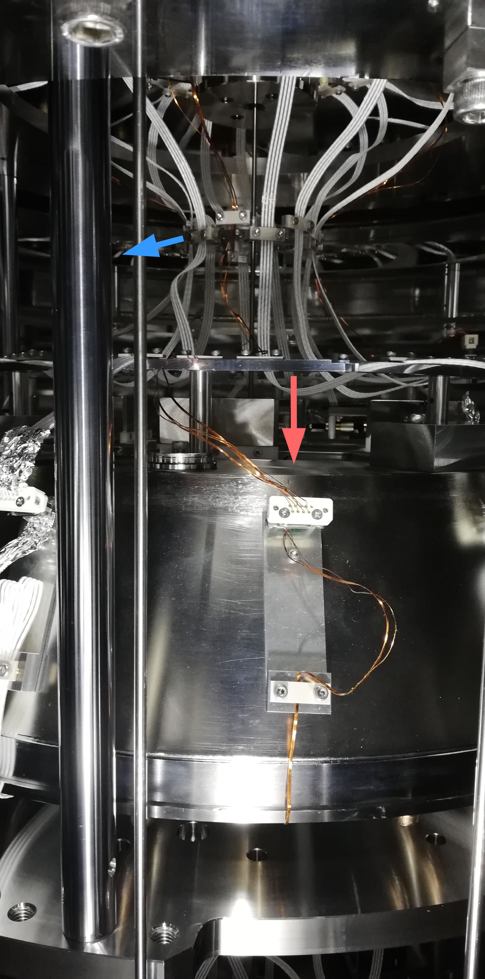
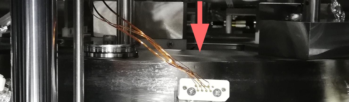
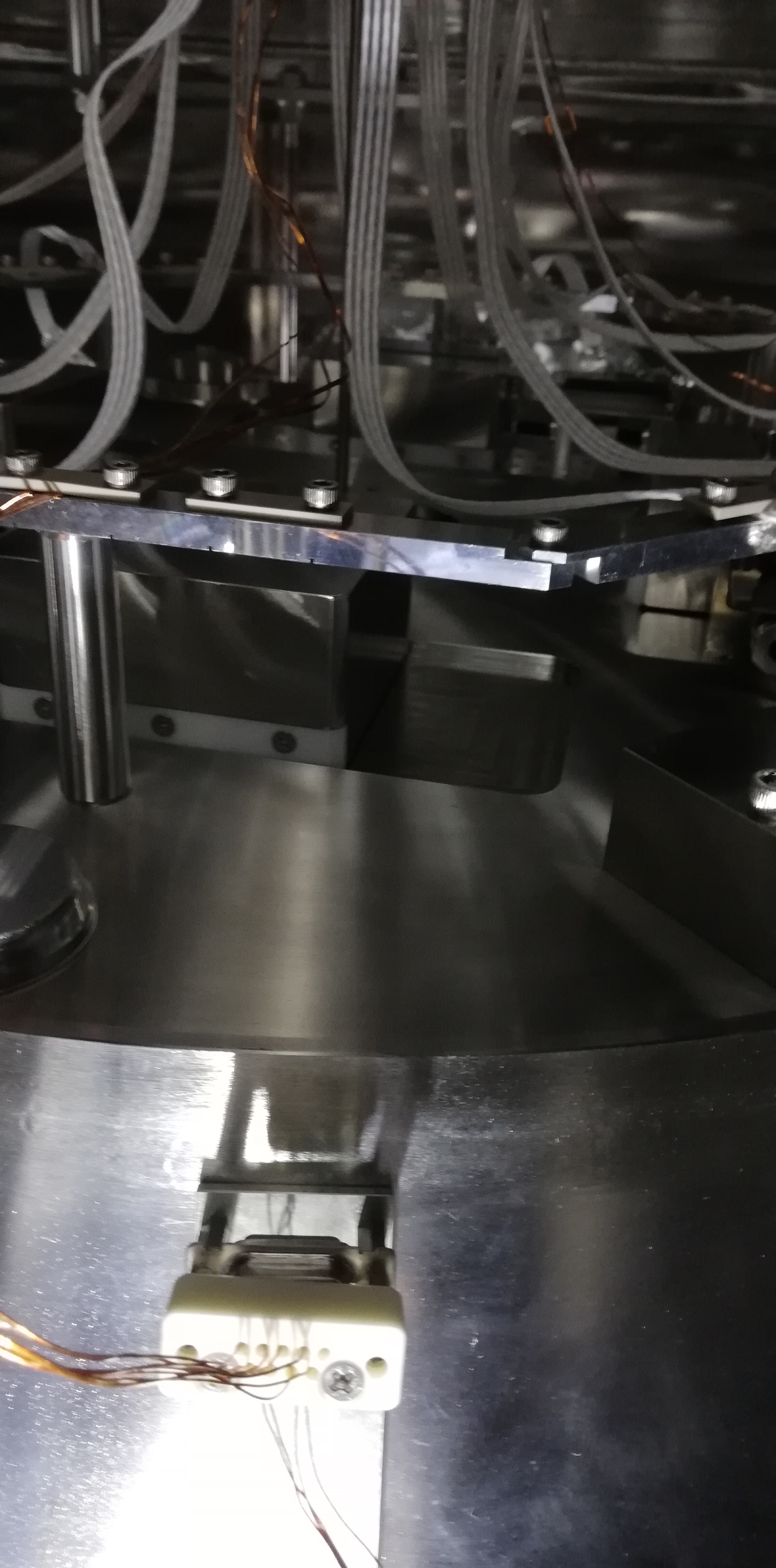
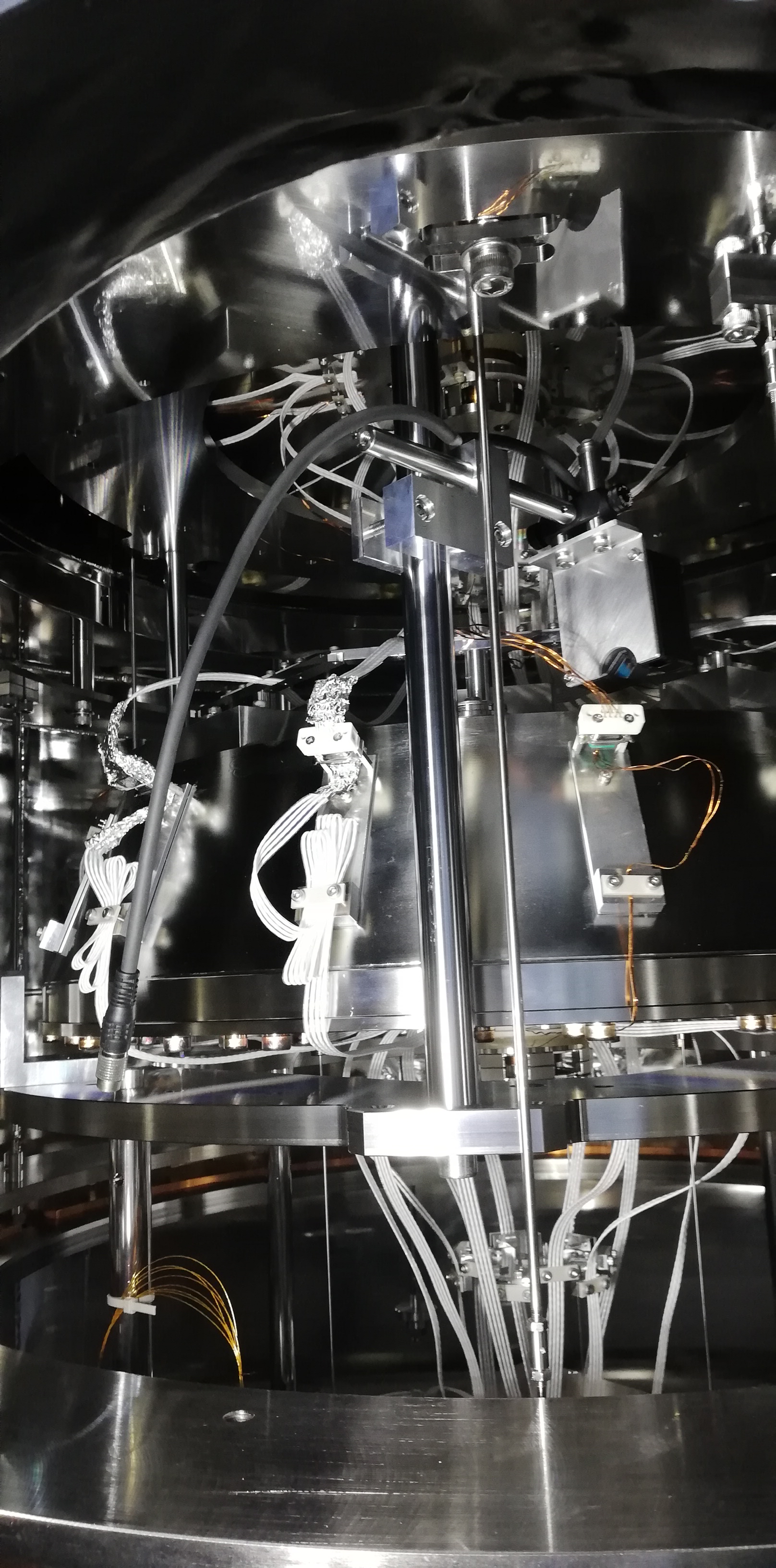
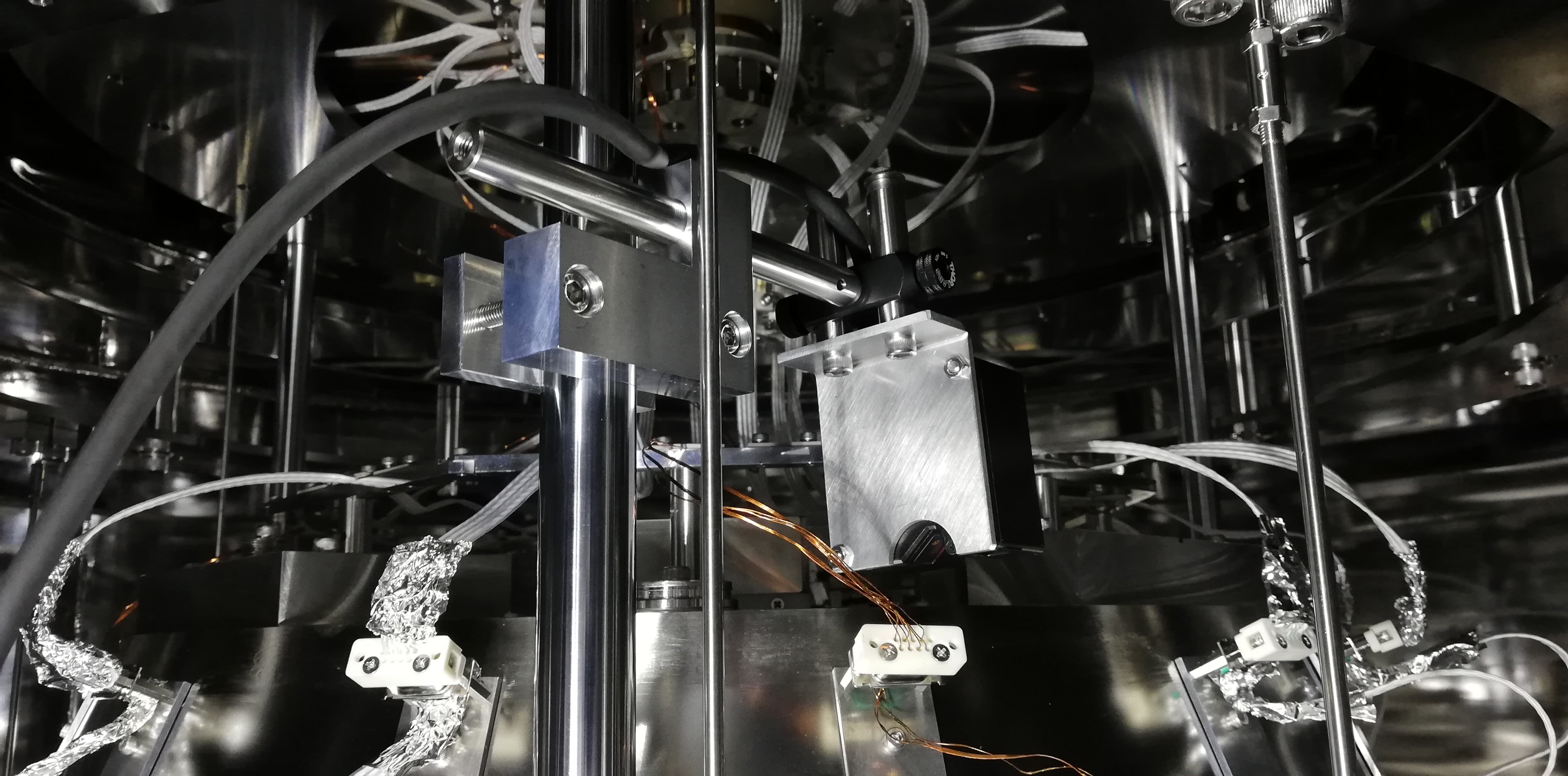
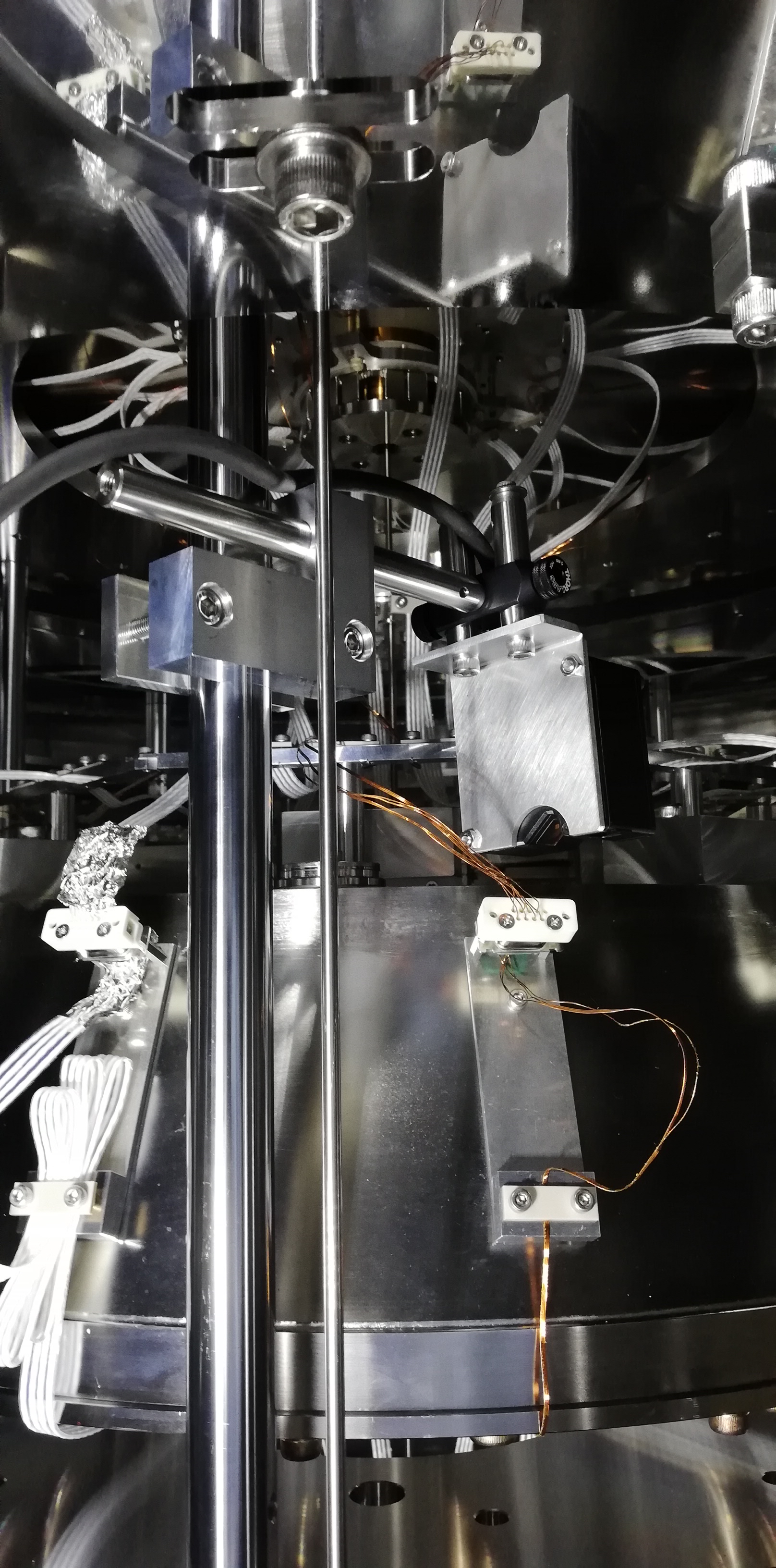
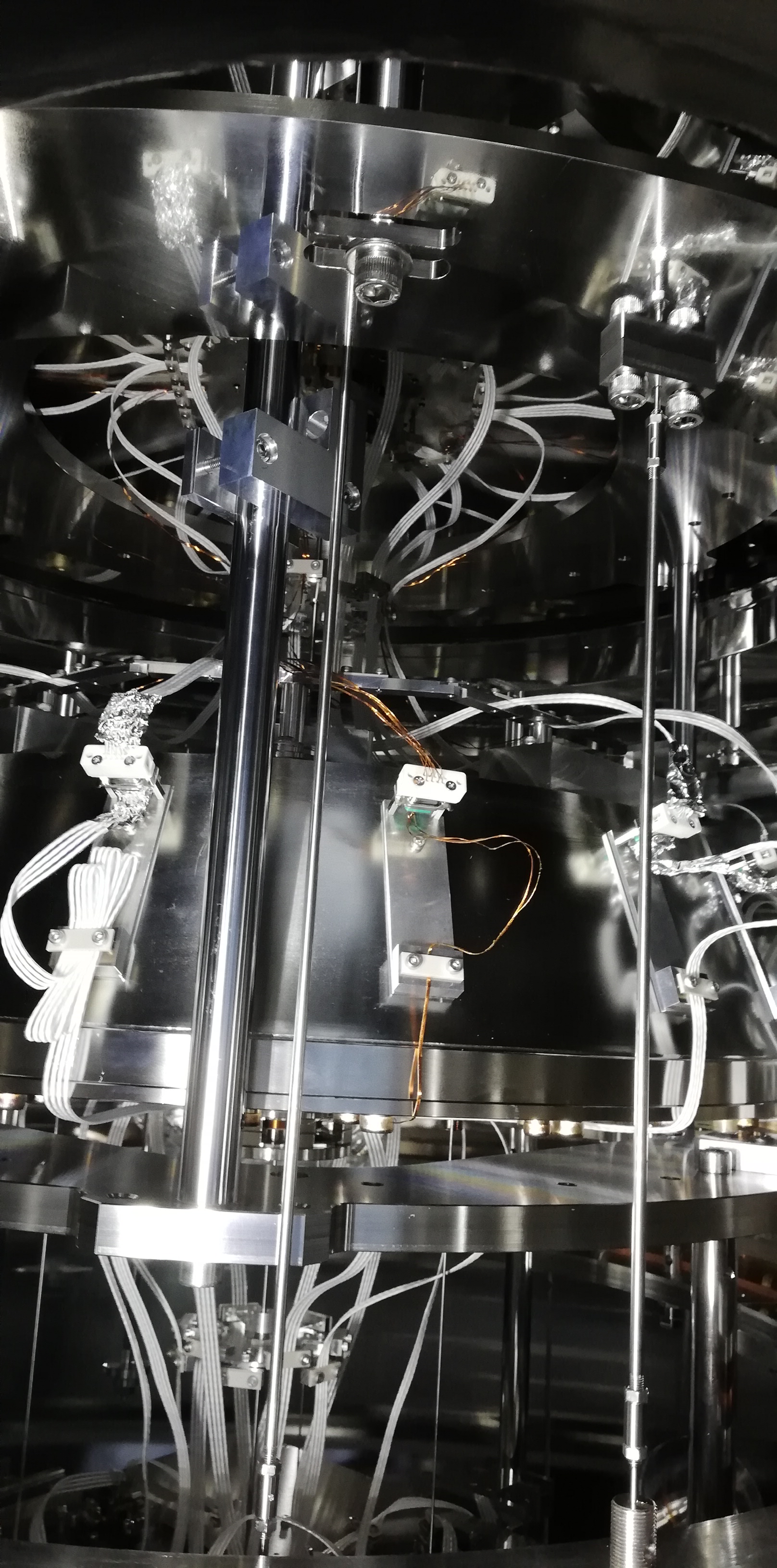
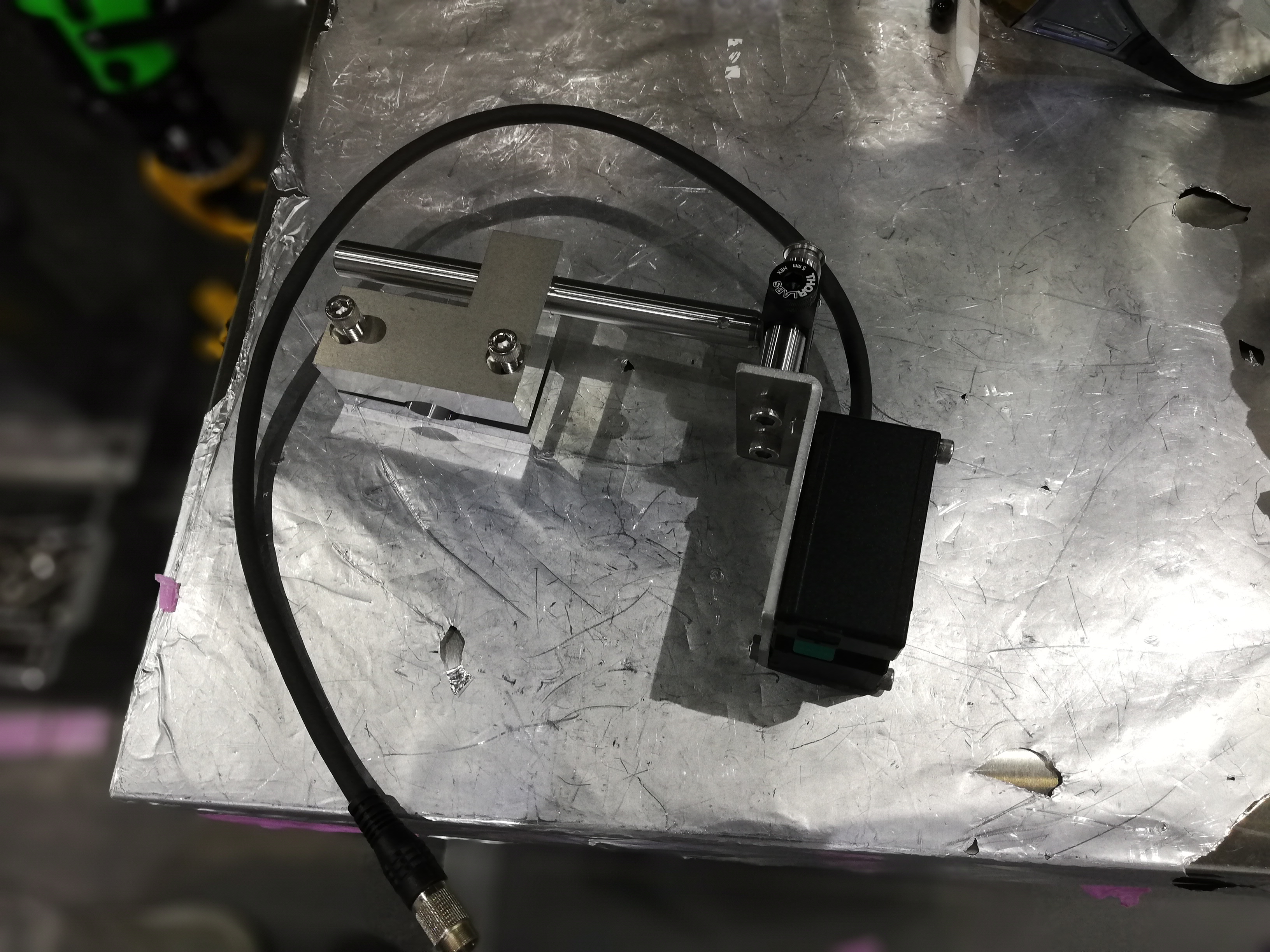
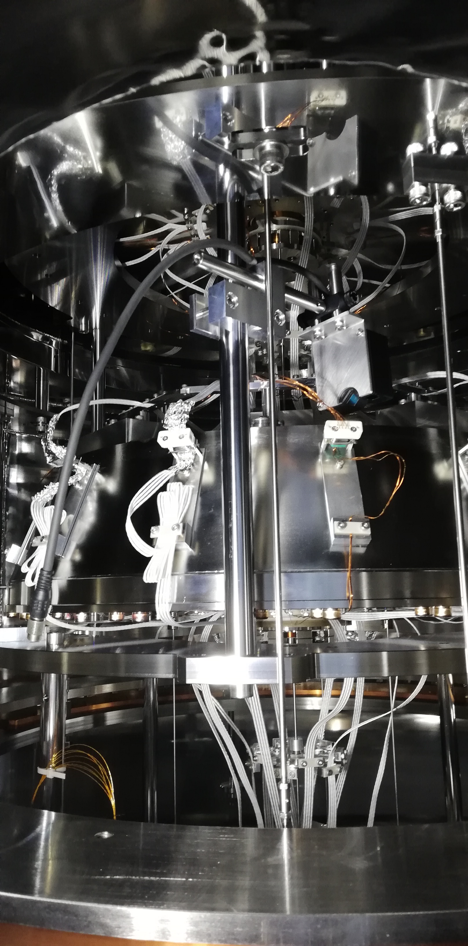
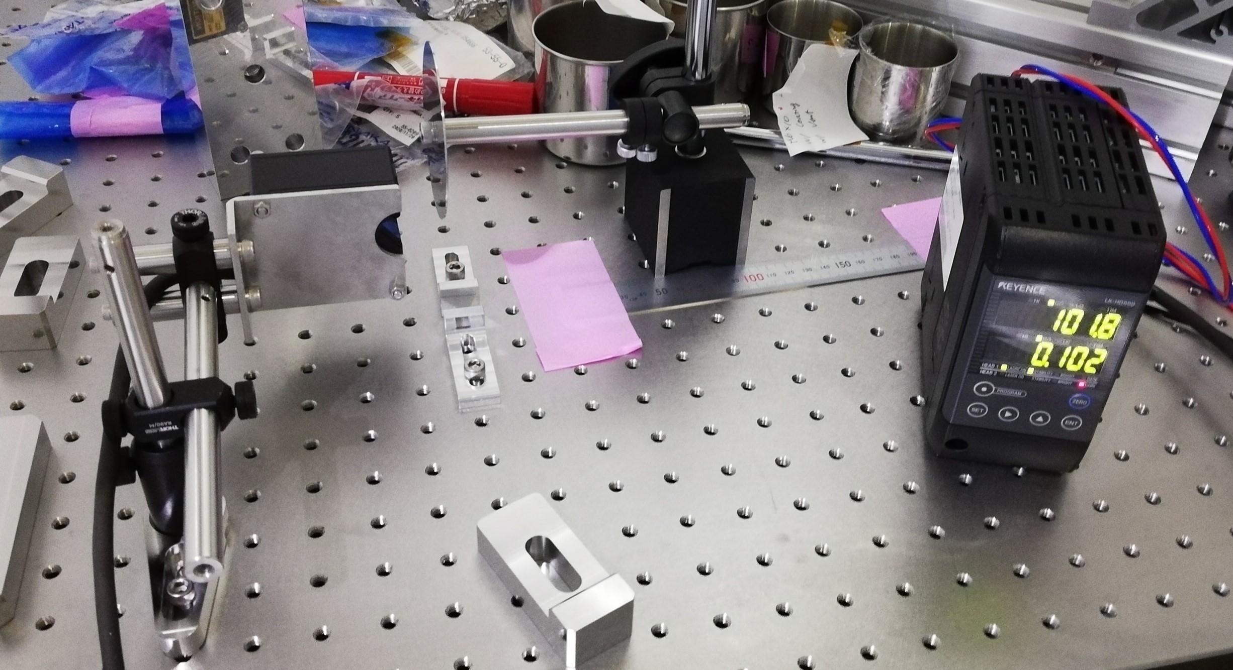
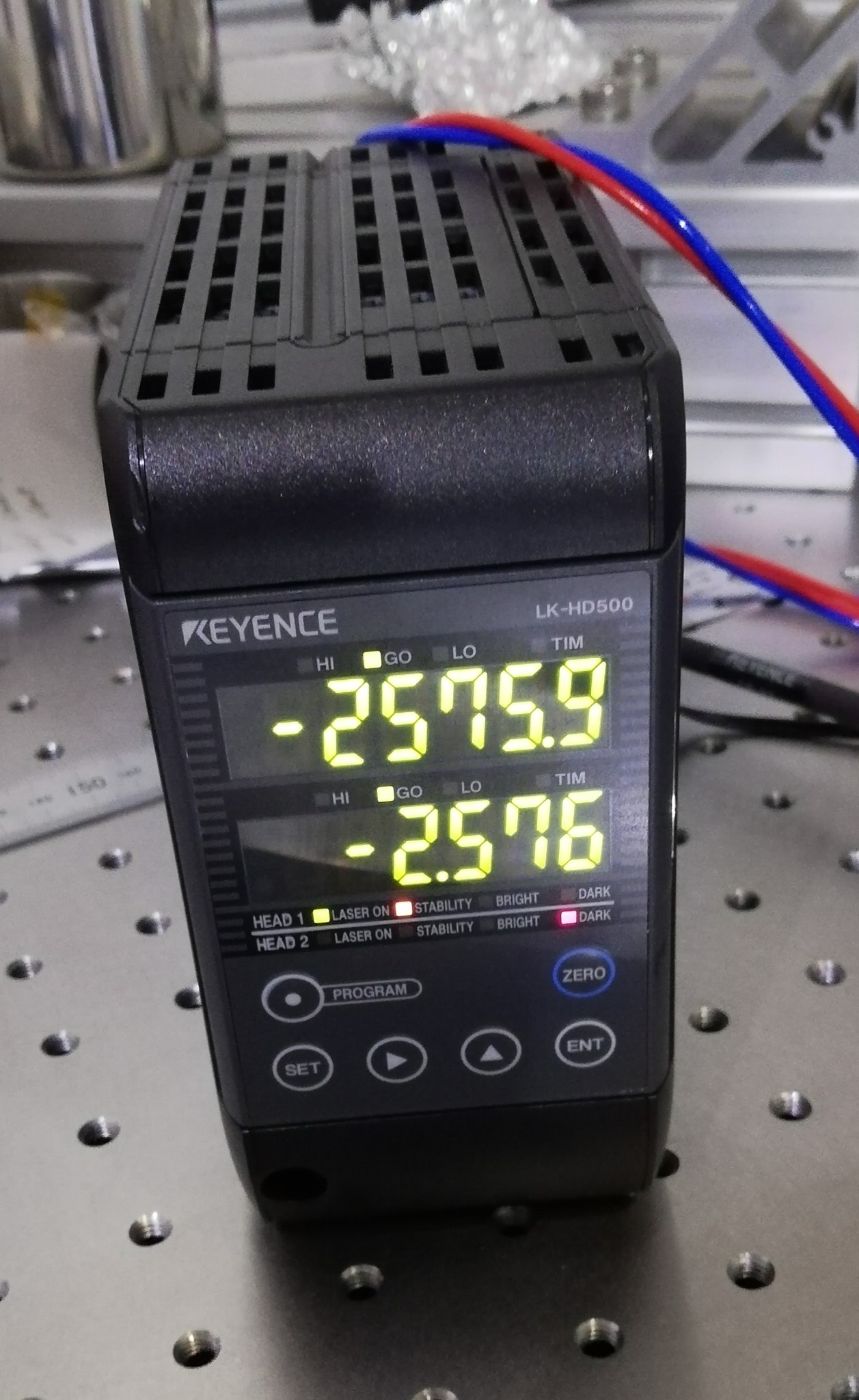
The sensor is the LK-H022K manufactured by Keyence. The principle of operation is a laser diode emiting light onto the target surface and a photo sensor measuring its reflection. We can mount it above the Bottom Filter in order to measure the displacement of the cap. The first picture shows the -Y side of the BF, which is accesible. The blue arrow indicates where a support arm can be anchored to a nearby pillar of the security structure, and the red arrow indicates the surface upon which the sensor would measure.

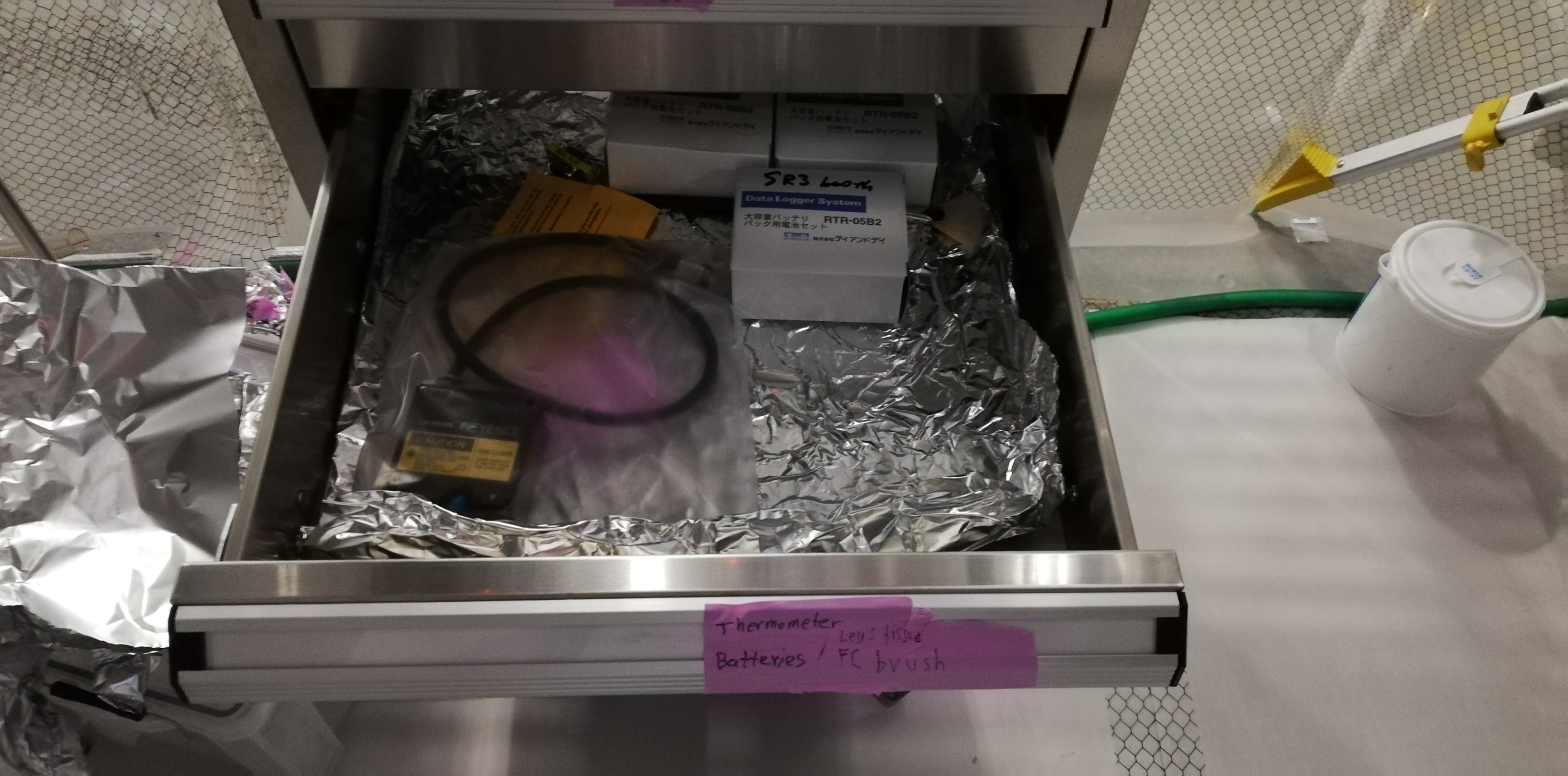
I put the sensor head in the chest of drawers next to SR2 chamber.

Images attached to this report
Comments to this report:
fabian.arellano - 21:39 Tuesday 14 December 2021 (19215) Print this report

With Hirata-san, Terrence and Zhao-kun.

This entry reports preparation work for the calibration of the F1 LVDT. We tested the hardware to mount the displacement sensor above the BF.

The hardware seemed to work fine, although it was challenging to mount it. It is a place of hard access and we were not expecting it to be easy. See pictures.

After we finished the test we removed the displacement sensor but left a bracket attached to the security structure. We aim to do the calibration next week.

Images attached to this comment
fabian.arellano - 17:15 Wednesday 05 January 2022 (19355) Print this report

With Hirata-san and Takahashi-san.

As preparation to use the displacement sensor to calibrate the F1 LVDT, we mounted the sensor on a table and roughly checked with a ruler it's workig as expected.

Images attached to this comment
fabian.arellano - 16:17 Friday 21 January 2022 (19529) Print this report

With Hirata-san.

See pictures in the album BS Remedying work after O3.

Summary: We aimed to calibrate the F1 LVDT with the optical displacement sensor, however, we realized the holder requires adjustment for an additional angular degree of freedom in order to achieve alignment.

The holder allows adjustment of the vertical and one angular degree of freedom. We successfully put the sensor approximately 20 mm above the surface of the BF and, by adjusting those two DoF, we nearly achieved the alignment. Sometimes the sensor came online during a few moments, but it never remained aligned.

Currently, we are thinking of ways to modify the holder.

Search Help
×

Warning

×