Reports 1-1 of 1 Clear search Modify search
VIS (PR3)
fabian.arellano - 16:35 Thursday 14 October 2021 (18572) Print this report
Lowering PR3 mirror.

With Hirata-san.

Summary: It is possible to lower the SF keystone 5.2 mm from the current setpoint.

See pictures in album PR3 Remedying Work.

In the context of the klog report 18562, we examined whether it's possible to lower the mirror by 5.2 mm using the SF only.

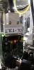
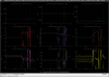
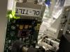
  • We locked the keystone at the current setpoint using the LVDT readout as a guide.
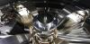
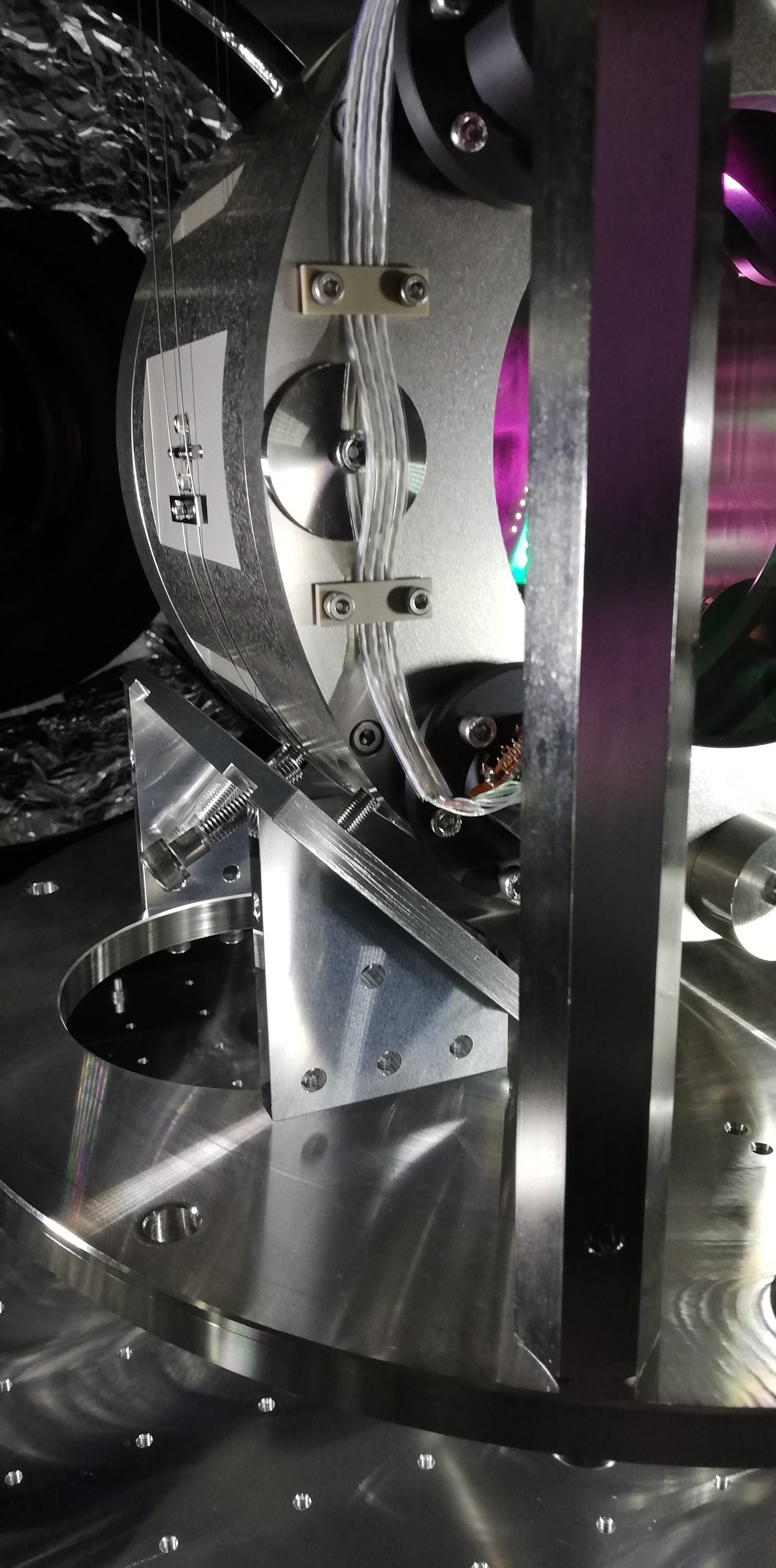
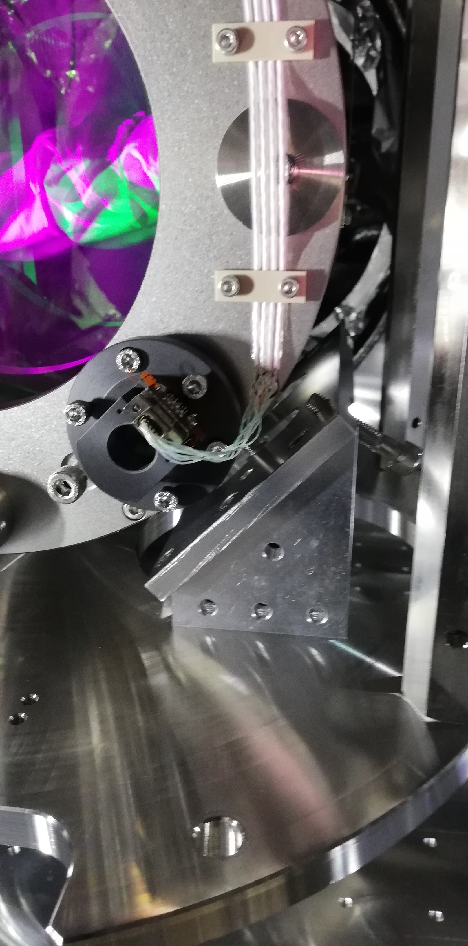
  • Using a vernier caliper, using the lock screws we carefully lowered the keytone by steps while checking the RM did not touch the security structure below.
  • The keystone was lowered approximately 5.5 mm. Because the surface supporting the caliper was not flat (a screw tip), it was hard to place the caliper in a reproducible way every measurement. The accuracy is likely within a few hundreds of micrometers.
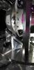
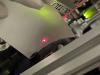
  • The major concern was whether the cables underneath the BF would touch the security structure ring. Nevertheless, there are still functional gaps even for the lowest cables.
  • The amount of ballast mass required to achieve such a displacement was 405 grams.

From this assessment, we think it's feasible to lower the mirror this way. There are additional notes:

  • Although we did not check, we expect the SF LVDT to be out of range at such a low position, therefore, we would  need to lower the yoke-coil assembly. The challenge will be to access the yoke assembly without damaging the cables around it.
  • The SF keystone would be lowered by adding mass to the SF load. It is far much better to add mass on top of the keystone than on top of the BF. Putting them on the BF would require balancing it, which we should avoid. Adding mass on the keystone would require an additional supporting plate, but that's easy to do.
Comments to this report:
fabian.arellano - 16:45 Monday 08 November 2021 (18800) Print this report

With Hirata-san.

See pictures in album PR3 Remedying Work.

We received the components we require to add ballast mass directly on the SF keystone, therefore, we proceeded with installation:

  • Hirata-san modified the main holder plate to enable us to install it without having to change the stud bolts in the keystone. With the modification, we only needed to move the studs 3 mm up in order to give space to the lock nuts.
  • After installation we added mass to the keysone:
    • Main holder plate: 106 g,
    • Six small screws: 2 g,
    • Ballast mass: 291 g.
    • Total: 399 g (aim was 405 grams)
  • The temperature was 24.6 °C (O3GK T= 23.1 °C).
  • We also changed part of the security structure underneath the RM for a shorter one. We still need to replace another part.
Images attached to this comment
fabian.arellano - 18:01 Tuesday 09 November 2021 (18818) Print this report

With Hirata-san.

Summary: We fishined the procedure of lowering the mirror using the SF keystone. The mirror is now 0.2 mm above the expected beam height when the GAS Filters are at their setpoints. Unfortunately, we disturbed the pitch of the mirror at the end.

See pictures in album PR3 Remedying Work.

  • First we lowered the yoke-coil assembly by approximately 5.2 mm
    • The screws holding such an assembly have a pitch of 0.8 mm, therefore, we did 6.5 turns of each of the three screws (see notebook for quatitative details).
    • Then we locked the assembly with the push screws.
  • Then we lowered the BF Damper
    • The pitch of the threaded receptacle of the Damper is 2 mm, therefore, we did approximately 2.6 turns of each of the nuts in the receptacles that hold the weight of the Damper.
    • We did it in two steps of 1 turn each (2 mm) and one step of 4/6 of a turn (1.3 mm), which is a total of 2.66 turns (5.3 mm).
    • We locked the BF for safety.
    • For each step we did the following:
      • We locked the BF Damper to the security structure.
      • We adjusted the position of the nut in only one of the receptacles.
      • We released the BF Damper so it would be again supported by the recently lowered nut.
      • We locked the BF Damper again and repeated the procedure for the nut in another receptacle.
  • After this change we measured the height of the mirror and adjusted it using the SF fishing rod.
  • We moved the keystone close to the setpoint. At such position, the height of the mirror was 0.2 mm above the expected beam height.
  • This result is not so surprising becuase we moved both the primary and secondary coils of the SF LVDT by approximately the same amount.
  • We disturbed the pitch of the mirror around the time in which we closed the chamber. See the picture of the oplev beam on the QPD board.
Images attached to this comment
takafumi.ushiba - 18:31 Tuesday 09 November 2021 (18821) Print this report

I checked the OpLev trend and found that PR3 jump happened yesterday (fig1).
Also, there are significant jump in the IM OSEM signals during today's work but it was smaller than yesterday's one (fig2).

Images attached to this comment
fabian.arellano - 16:36 Wednesday 10 November 2021 (18829) Print this report

With Hirata-san.

Summary: We recovered the pitch alignment of the mirror. According to TF measurements, the IM stage looks relatively healthy, but more measurements are required.

We adjusted the pitch of the mirror using the IM picomotor. Namely, we needed to decrease the amount of pitch.

  • As pointed out in entry 18314, pressing the button "REV" moves  the mirror in negative pitch.
  • We also had to adjust yaw, but by a very small amount.
  • We noticed there's a stray beam almost reaching the tilt QPD. See the pictures. It would be good to get rid of it.
  • After we set the oplev beam at the QPD centre, the V1 OSEM readout became 2,400 counts with the BF at -307 um from the setpoint, which is likely within linear range of the OSEM. However, when we set the BF keystone to the setpoint its readout became about 1300 counts, which is liklely out of linear range.
  • I proceeded to measure transfer functions of the IM. I didn't measure all of them because, according to the OSEMs, the IM stage looked relatively healthy, so I handed the suspension to the green laser alignment team.
    • The first two screenshots show the TFs in V and P with the BF at the setpoint. The amplitude in the one for P show a smaller amplitude, but it might be an acceptable compromise. The one for V shows low coherence between 150 to 500 mHz and an unexpected peak just above 300 mHz. We need to check this.
    • The other TFs shown were measured with the BF at -307 um away from the setpoint. I measured at that position because it favored the V1 OSEM readout but there's no suggestion for chaging the setpoint. The TF for V shows the same strange peak just above 300 mHz.
Images attached to this comment
fabian.arellano - 14:51 Thursday 11 November 2021 (18840) Print this report

Summary: I investigated the peak that appears in the IM-V transfer function at 343 mHz and the low coherence observed between 150 to 500 mHz. I also measured transfer functions using the BF Damper. The system looks healthy.

  • I used a resolution of 10 mHz and 5 averages.
  • The screenshots show the transfer functions for IM-V, BF-GAS and SF-GAS.
  • In the three of them the peak at 343 mHz appears. Additionally, the feature at around 260 mHz that appears in the reference plots dissapears in the new measurements.
  • This suggests that the change was due to the lowering of the SF keystone by 5.2 mm. This is, the system is healthy.
  • The second peak also moved in frequency by a small amout: it moved from 625 to 664 mHz approximately.
  • The low coherence in the IM-V measurement was due to a low amount of actuation applied at each of the vertical OSEMs. From 4,000 cnt I incresed it to 25,000 cnt in IM-V, which converted to ±700 cnt at each OSEM. This produced a better coherence.
  • The BF Damper transfer functions look fine, it seems there is no major problem:
    • The recorded references for the phase in some measurements is wrong, so comparison cannot be made.
    • The references were measured with 30 mHz resolution and only 3 averages, which is not so suitable.
    • In the TFs for P,  R, V the amplitue of the new measurements are larger than the reference above 10 Hz. These correspond to the vertical LVDTs.
Images attached to this comment
fabian.arellano - 16:18 Friday 12 November 2021 (18869) Print this report

With Yasui-san.

Today we changed part of the security structure underneath the RM for a shorter one. On Monday we replaced the other part, so the replacement is now complete.

Images attached to this comment
Search Help
×

Warning

×