I continued the adjustment of PR3 by adjusting the pitch of the BF.
As usual, the suitability of this method depends on the compromises we can or are willing to tolerate. In general, the compromises that would be expected, and the measurements to assess them, are the following:
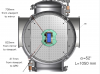
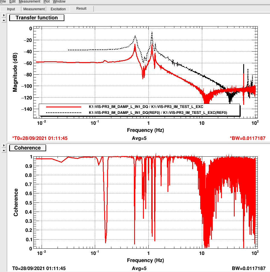
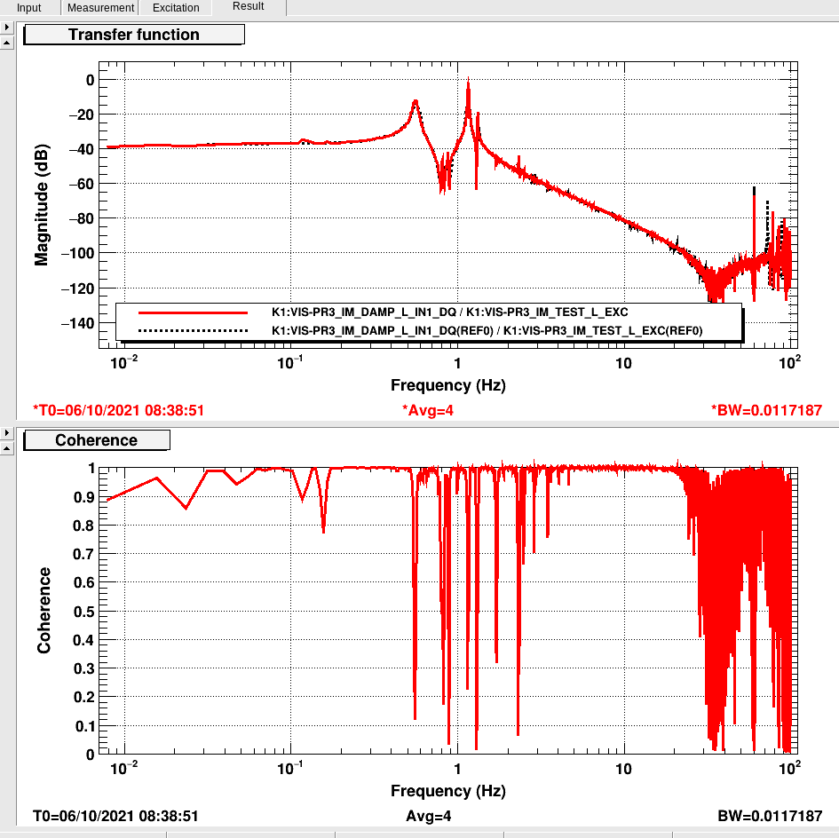
- OSEM H1 going out of linear range, IM-L transfer function.
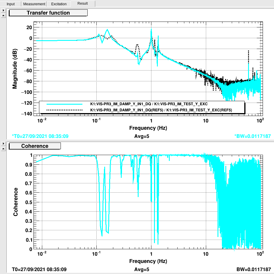
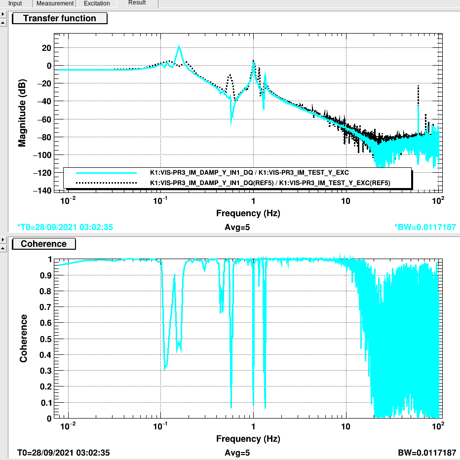
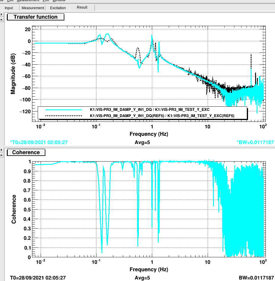
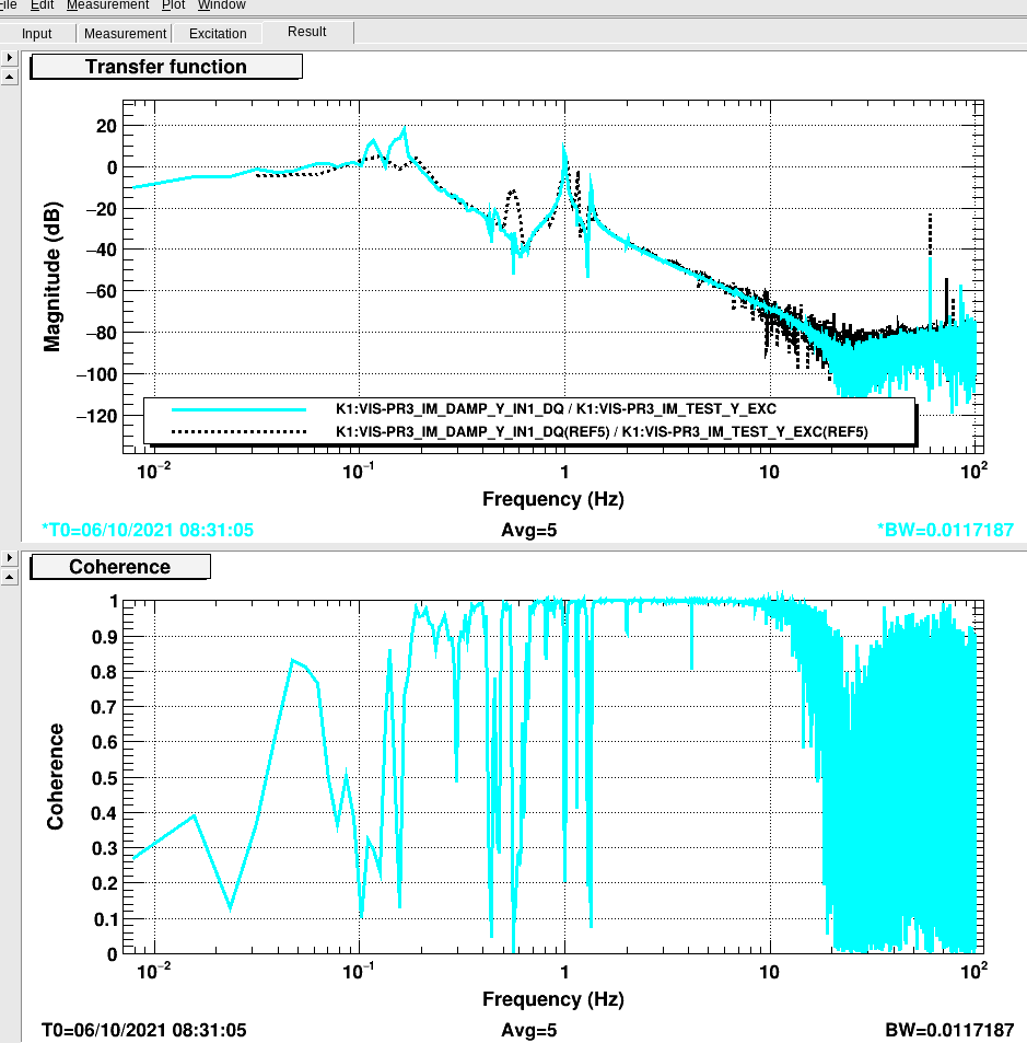
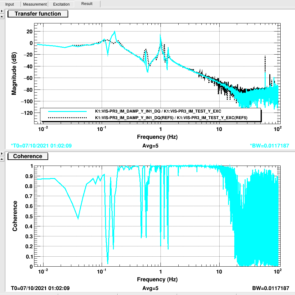
- OSEM flags H2 and H3 touching their respective OSEM bodies, IM-Y transfer function.
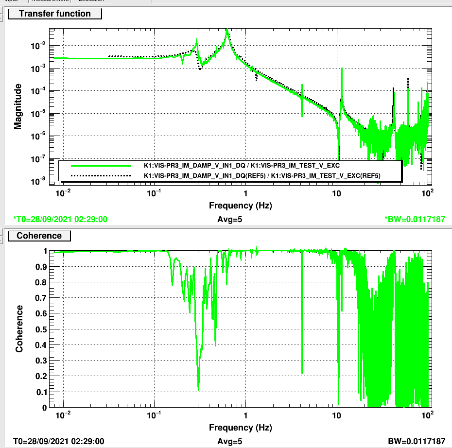
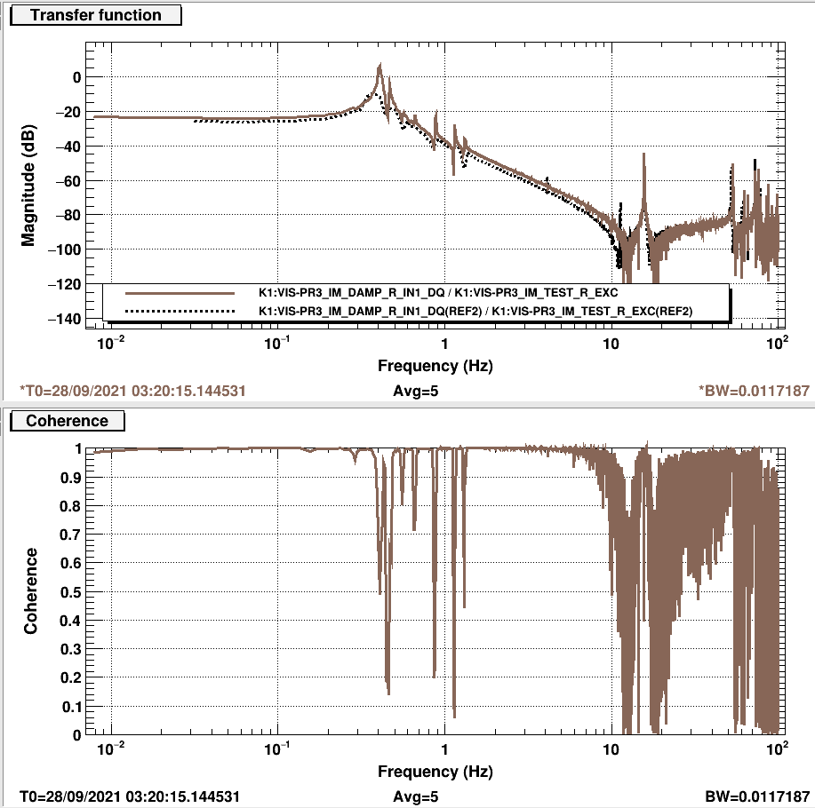
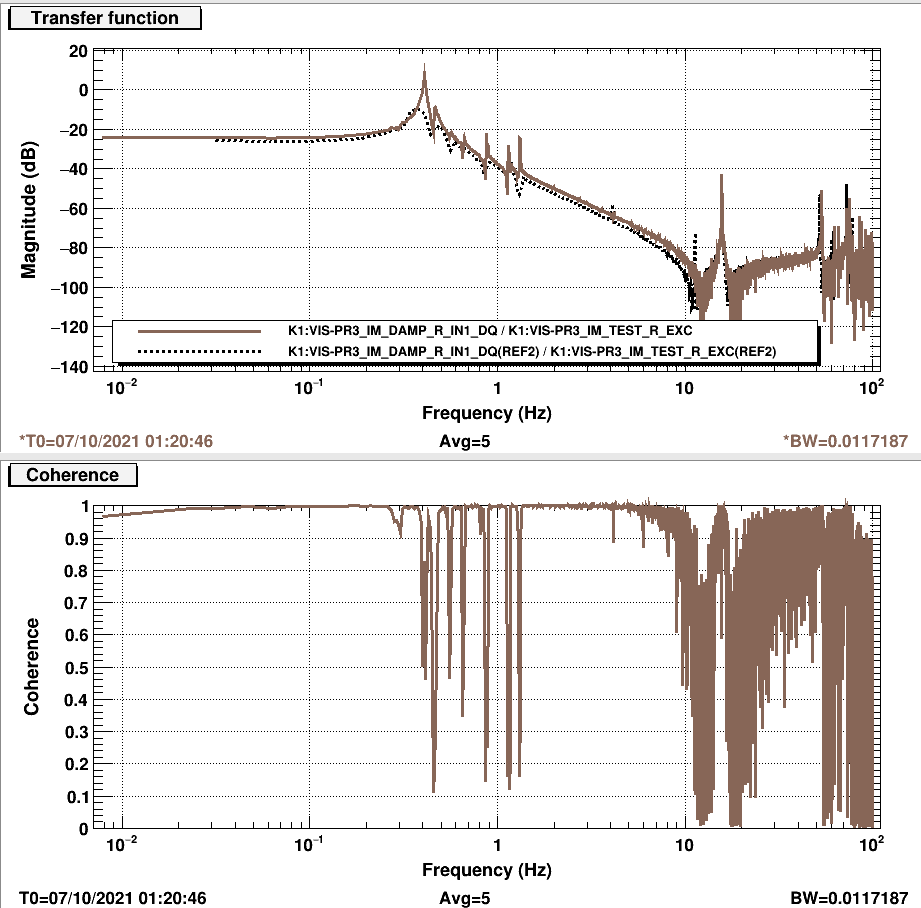
- OSEMs V2 and V3 going out of linear range, IM-R transfer function.
Of course, we can in principle know whether an OSEM is within range by looking at its output. However, when we're in doubt we should measure the transfer function.
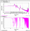
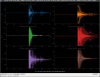
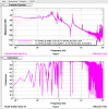
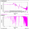
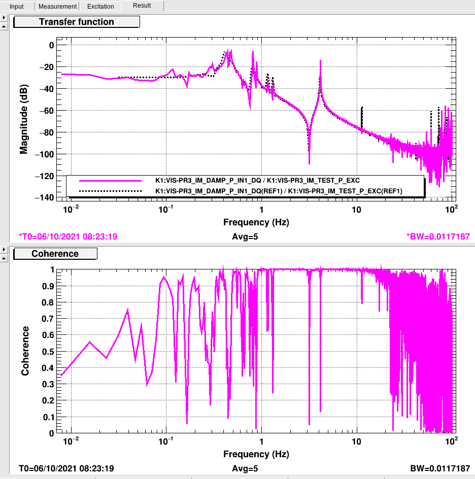
From the tests I've carried out so far, it seems that the most important compromise is item 1, the range of H1 OSEM. So far, I've tested two configurations described by the V1 OSEM readout: 500 count and 790 counts. The screenshots show transfer functions measurements groups by pair of the same kind.
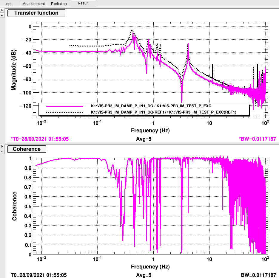
The case of V1 having 500 counts
- H1 readout is 9560 counts, which is converted into -102 um.
- Displacement measured by H1 from the position in which V1 was not usable: 300 um.
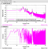
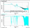
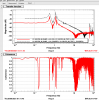
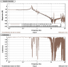
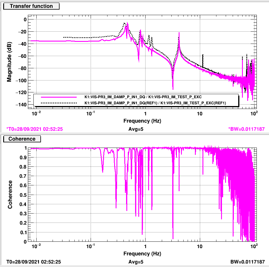
- In the transfer function IM-P, at low frequencies the amplitude decreases about 8 dB (2.5 times) with respect to the reference.
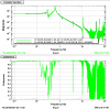
- In the transfer function IM-L, at low frequencies the amplitude decreases by more than 5 dB (1.8 times) with respect to the reference.
- Additionally, in IM-L the frequency at which the noise becomes dominant decreases from ~35 Hz to ~26 Hz.
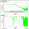
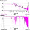
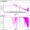
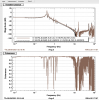
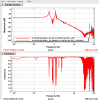
- The transfer fiunctions for R, Y and V look fine.
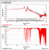
The case of V1 having 790 counts
- H1 readout is 10,160 counts, which is converted into -147 um.
- Displacement measured by H1 from the position in which V1 was not usable: 345 um.
- In the transfer function IM-P, at low frequencies the amplitude decreases about 5 dB (1.9 times) with respect to the reference, an improvement of 3 dB from the previous case.
- However, amplitude of the IM-L the transfer function decreases by 20 dB (10 times) with respect to the reference.
- In IM-L, the frequency at which the noise becomes dominant decreases to almost 10 Hz.
- The transfer fiunctions for R, Y and V look fine.
Using the information from both configurations, the displacement of H1 per displacement of V1 is 45 um / 290 cnt = 0.155 um/cnt.
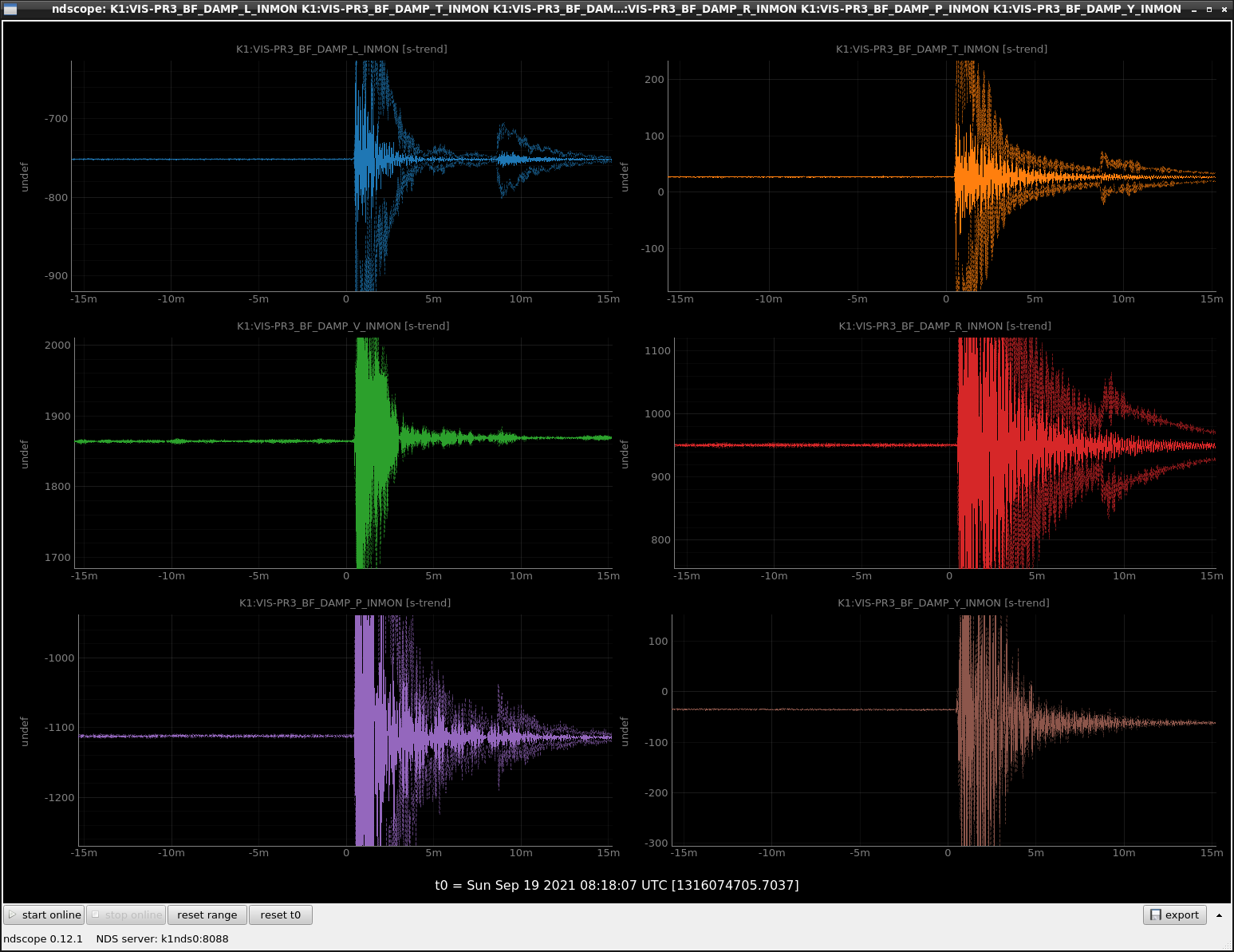
Additional observations
The position of H1 when V1 was not usable was 200 um (5500 cnt). This means that we could move H1 OSEM to a smaller number of counts in order to increase the amount of correction we can achive using this method.
Right after the earthquake, the readout of V1 OSEM was 6772 cnt, V2 3280 cnt and V3 1931 cnt. This suggests that we could move V1 such that its readout increases by 2000 counts and it could still be usable in both configurations.


