Abstract
Without changing a total transfer function, we modified individual TF of DAMP and DC filters avoid (maybe) a numerical rounding errors.
DC filter should be set after DAMP filter as reported in klog18249.
If some numerical error occurs on DAMP filter, DC filter doesn't seem to work well.
Details
After swapping the filter module order as FM3=DAMP, and FM4=DC reported in klog18249, error signal of F0 go around 20 (not around 0).
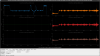
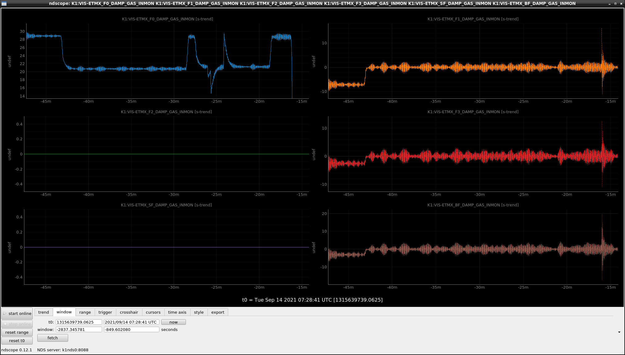
Fig.1 shows the error signal just after engaging F0 loop [t=-43m] and giving offset [t=-25m, -24m etc.]. Pls. see only F0 signal (blue curve).
We doubt the control doesn't work at all. But when offset is given from F0_TEST_GAS, error signal always go around 20 by some kind of feedback.
This problem was able to be solved by re-swapping filter order as FM3=DC, and FM4=DAMP.
So in order to solve both glitch and non-zero error signal problems at the same time, we tried to modify the DAMP and DC filters.
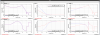
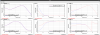
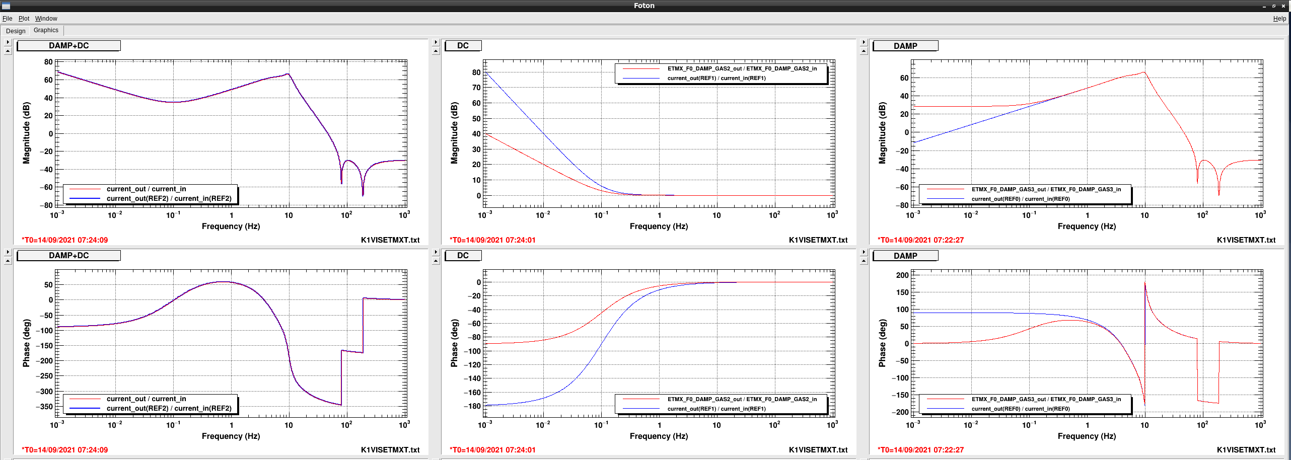
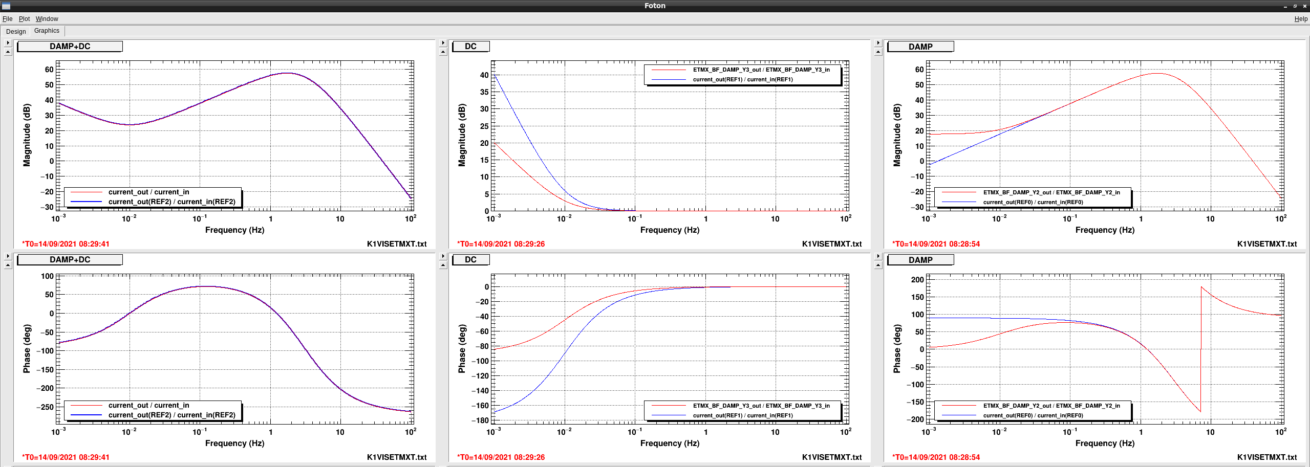
Fig.2 shows filters before (blue) and after (red) modification.
In originally, DAMP filter is f^1 in low-frequency and DC filter is f^-2.
Because we doubt output of DAMP filters was contaminated by numerical errors DAMP filter was changed as flat TF below 0.1Hz.
In order to keep total transfer function, DC filter was also changed as f^-1 below 0.1Hz.
In this implementation, both glitch and non-zero error signal problem was able to be solved.
IP filters were already implemented as f^-1 for DC and flat for DAMP below 0.01Hz.