With Hirata-san, Ikeda-san and Yasui-san.
We finished checking the health of the in-vacuum cables and we found one problem which is of concern: one of the pins for the IM pitch picomotor has a conductive path to the chamber, which is the ground. The details are:
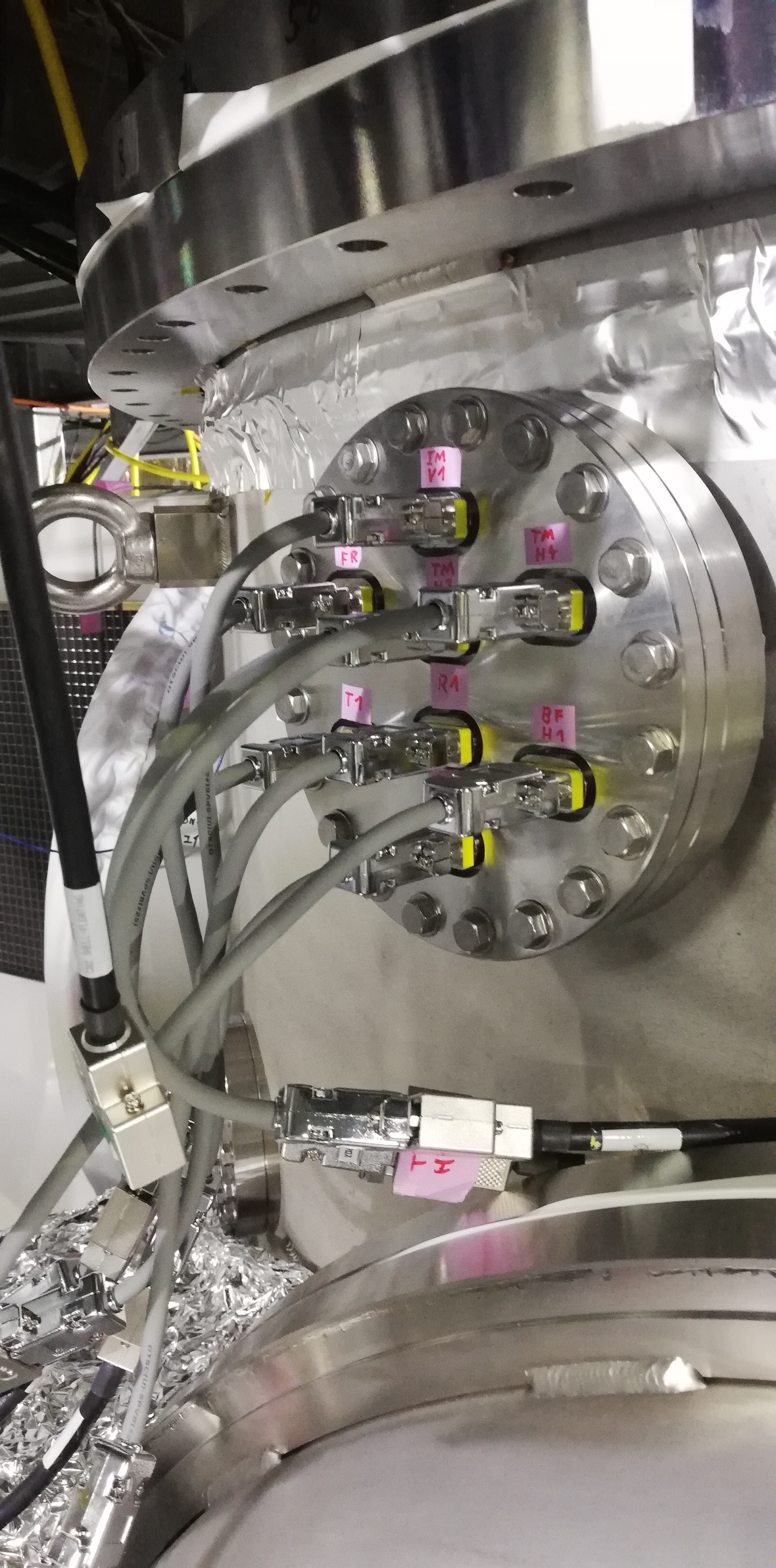
- Flange: 1
- Connector: 6
- Pin: 1
- Symptom: There is a conductive path with very low resistance between this pin and the chamber.
According to the wiring diagram (D1503615-v1 page 4), pin 1 of the connector is connected to pin 3 of the driver, which is labeled as MOTOR. The other picomotor terminal, which is pin 6 in the connector, is conected to pin 4 in the driver, which is the ground. This suggests there is a problem.
I suggest to do the following:
- Confirm the status of the motor by moving it and checking the mirror pitch orientation using the oplev.
- Becuase this picomotor was healthy in O3Gk, possible damage to the cable might have been inflicted at the upper part of the suspension when we opened the chamber and worked on the SF a few months ago. We should open the chamber and check.
- Change the polarity of the motor by exchanging the places of pins 1 and 6. This can be done outside of the chamber.
We also found a conductive path between pin 5 and the chamber in the IM-H3 OSEM cable in flange 1, connector 5. This is not a problem because pin 5 will be connected to ground when the in-air cable is connected.