We found circuit noise level is quite difference between PLL-X and PLL-Y on MIXER_DAQ and SLOW_DAQ in unlocked state yesterday night.
So I checked where noise comes from.
Finally I found CMS for X seems to be noisy compared with one for Y.
Details
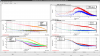
Fig.1 shows spectra of MIXER_DAQ and SLOW_DAQ in various situations.
At first I unplugged Dsub cables between the CMS and AA.
In this situation, noise level is roughly consistent with ADC noise level.
Red and blue curve in left panels represents the spectra in this situation for PLL-X and PLL-Y, respectively.
(Note: for SLOW_DAQ, compensation filter of generic filter "zpk([100,100], [10,10])" is applied.)
According to these spectra, ADC and AA seem to be healthy.
Next, Dsub cables were re-plugged. This is same situation in yesterday night and guardian was in DOWN state.
Spectra of PLL-X and PLL-Y were represented as orange and green curve in left panels, respectively.
Only PLL-X has noise excess as 10-100 times larger than ADC noises in MIXER_DAQ.
At SLOW_DAQ, both PLL-X and PLL-Y has noise excess from ADC noise. But PLL-X is more noisy than PLL-Y.
Because input switch of CMS was turned off in DOWN state, signals at DAQ ports should contains only ADC, AA, and CMS noises.
Even in DOWN state, compensation filter in common path is still turned ON.
So I also measured spectra after turned off compensation filters. (See magenta for PLL-X and cyan for PLL-Y curves in left panels.)
For PLL-Y, noise level at SLOW_DAQ got close to ADC nosie level, but for PLL-X, noise excess still remained.
Right top panel shows the spectrum ratio between turning ON and OFF the compensation filter.
Compensation filter for PLL CMS is z4000;p40, measured ratio of PLL-X follows the model function above 100Hz.
This means noise at SLOW_DAQ is probably limited by some noise coming from the upstream of compensation filters in common path.
(I will also compute input referred noise later.)
Finally, I also try to swap the connection between the CMS and AA.
Right middle and bottom panel shows the comparison between the spectra with cable swapping.
Red and blue curve shows nominal cable connection for PLL-X and PLL-Y, respectively.
Green and brown curve shows curcuit noise of CMS-Y+AA-X+ADC-X and CMS-X+AA-Y+ADC-Y, respectively.
Noise excess from ADC noise level can be seen on the spectra of CMS-X side.
So this means noise excess surely comes from the upstream of AA
instead of the interaction between CMS and AA+ADC such as large electric potential difference.