Yuzurihara, K. Tanaka
related to 17227
We found that the beam shape in front of MCE TRANS QPDs is strange, it seems to be clipping. So we examined the beam on the MCR table to see if it was clipped anywhere. and we found that clipping is occurred at BS3 in Figure 1 (https://gwdoc.icrr.u-tokyo.ac.jp/DocDB/0101/D1910144/002/MC_TRANS1.pdf)
### What we did
Figure 1 shows the optical layout of the MCE TRANS surface plate. the optical layout of the MCE is divided into two paths, one from BS1 to the transmission PD and the other to the QPD.
We checked the beam shape from upstream to see if there was anything wrong. First, we checked the path to the PD. Figures 2, 3, 4, and 5 show the shape of the beam after passing through the periscope, through the L1 lens, before the TRANS_PD, and before the TRANS_CCD. As far as we can see, no particular clipping seems to occur on the path toward the transmission PD.
We then examined the path to the QPD. Figure 6 shows the shape of the beam in front of QPD2. Looking at it, the shape of the beam appears to be an ellipse spread out horizontally. Sorry for the lack of pictures, but through the same investigation, we noticed that the shape of the beam changed before and after BS3.
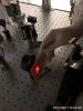
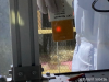
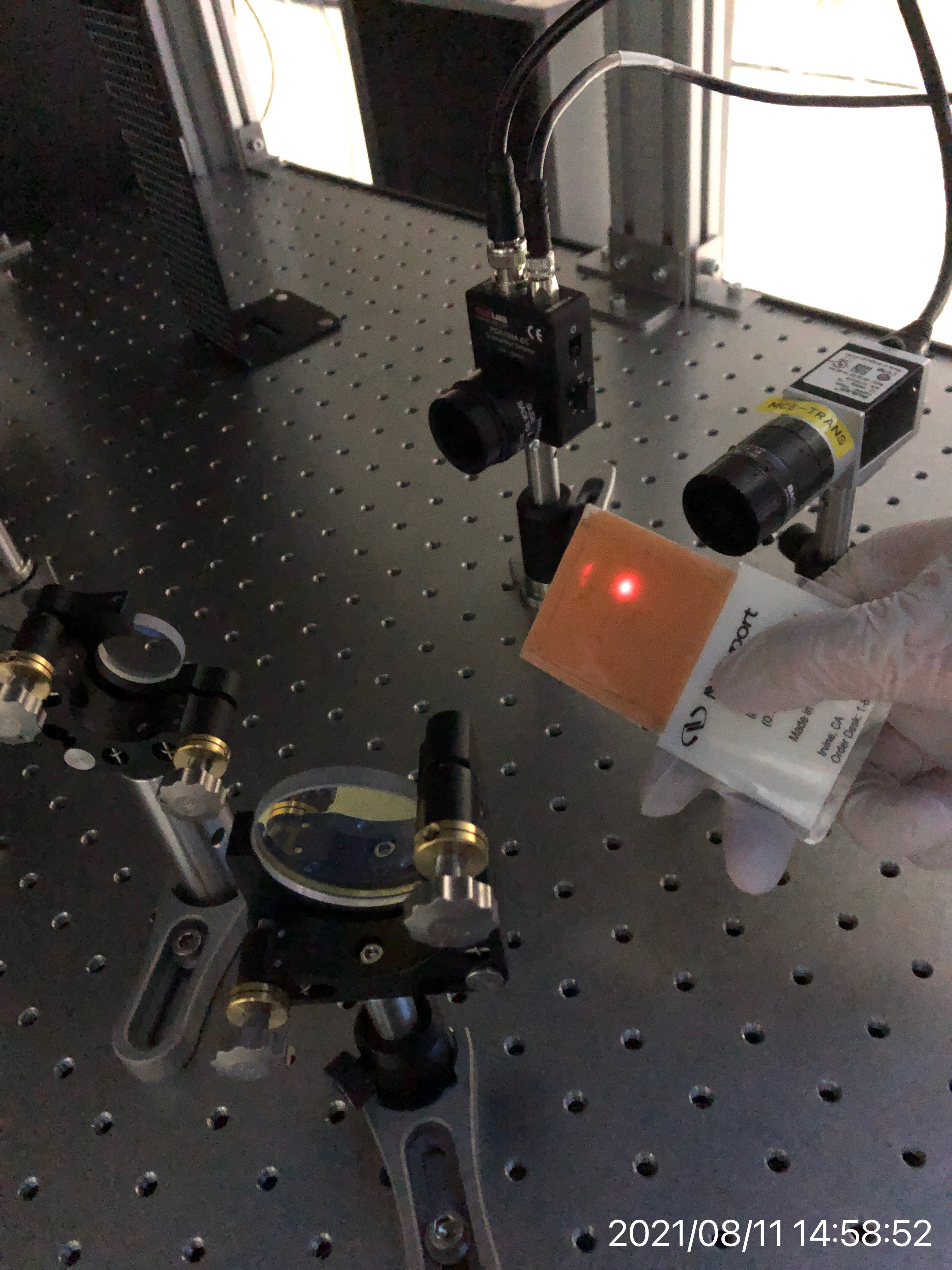
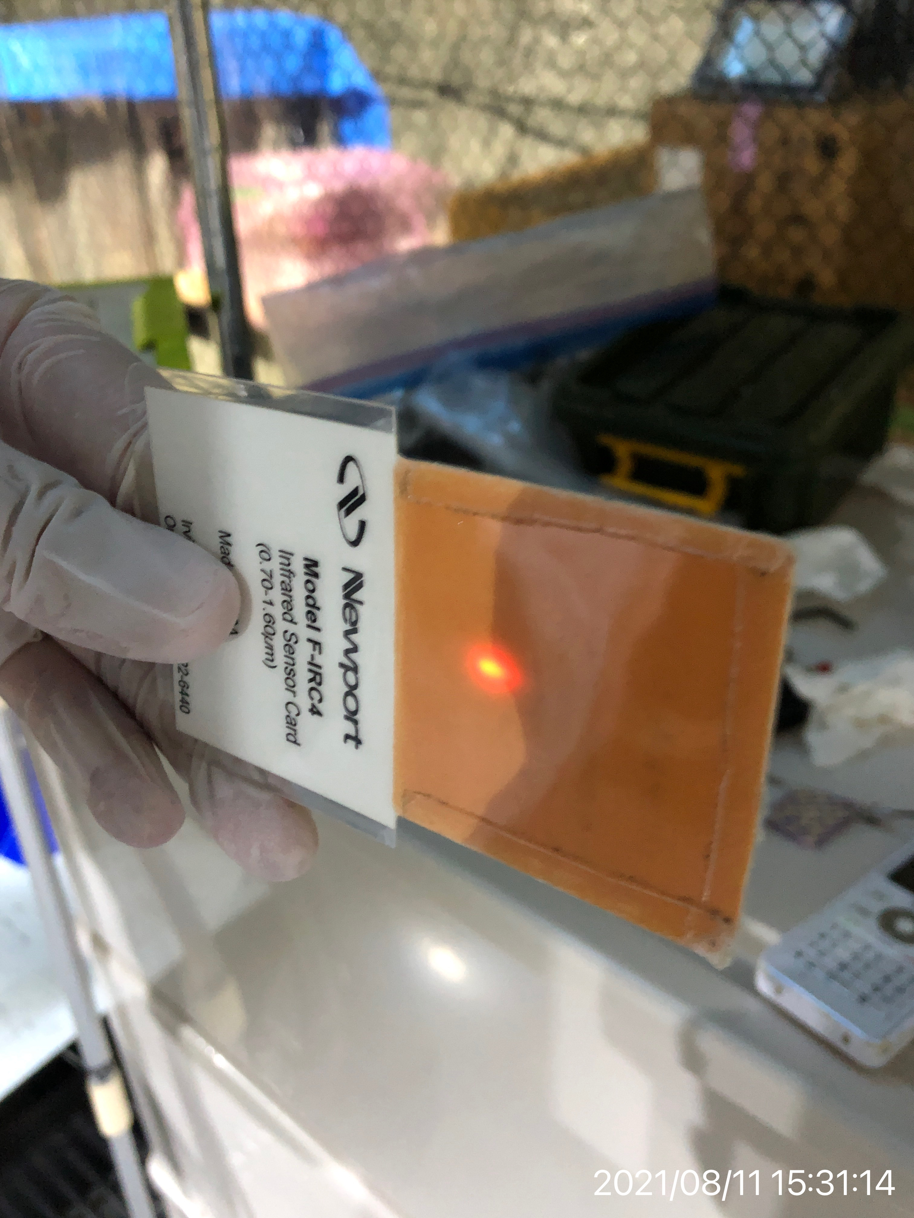
Therefore, due to space constraints, we set a pick-off mirror upstream from BS3 between lens L2 and mirror M2 to send the beam to a distant location and observe the shape of the beam there. Figure 7 shows the shape of the beam as seen by the sensor card, and Figure 8 shows the shape of the beam as seen by the beam profiler. As far as we can see, no particular clipping seems to occur at least before lens L2.
On the other hand, we set up a pickoff mirror between BS3 and QPD1. Figure 9 shows the shape of the beam as seen by the sensor card, and Figure 10 shows the shape of the beam as seen by the profiler. As you can see, the beam has a teardrop shape. Similarly, the shape of the beam as seen by the beam profiler when placed on BS3 and mirror M3 is shown in Figure 11. Here, too, we can see that the beam is teardrop-shaped. In other words, clipping is occurring at BS3.

