Past lock trial with heater feedback: klog#17464.
Abstract
With Izumi-san's advice, I tried the FNC-Y lock without temperature control and found that we was able to lock it more that 1hrs.
We may be able to solve the rack space problem in ASC0 rack related to new PZT mirrors on POP/POS tables.
A NIM module as heater driver uses 5U space in ASC0 rack (See also Fig.3 in klog#17616).
Details
I requested PHASE_LOCKED state to FIBY guardian with stopping DAC output to the heater actuator.
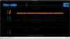
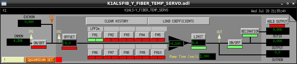
In order to stop the DAC output, I changed the swich configuration of K1:ALS-Y_FIBER_TEMP_SERVO shown in Fig.1.
Specifically, I turned off an input switch and an offset switch because an output switch was managed by Guardian.
Finally, I was able to check that we can lock FNC-Y more than 1hrs. without the heater feedback.
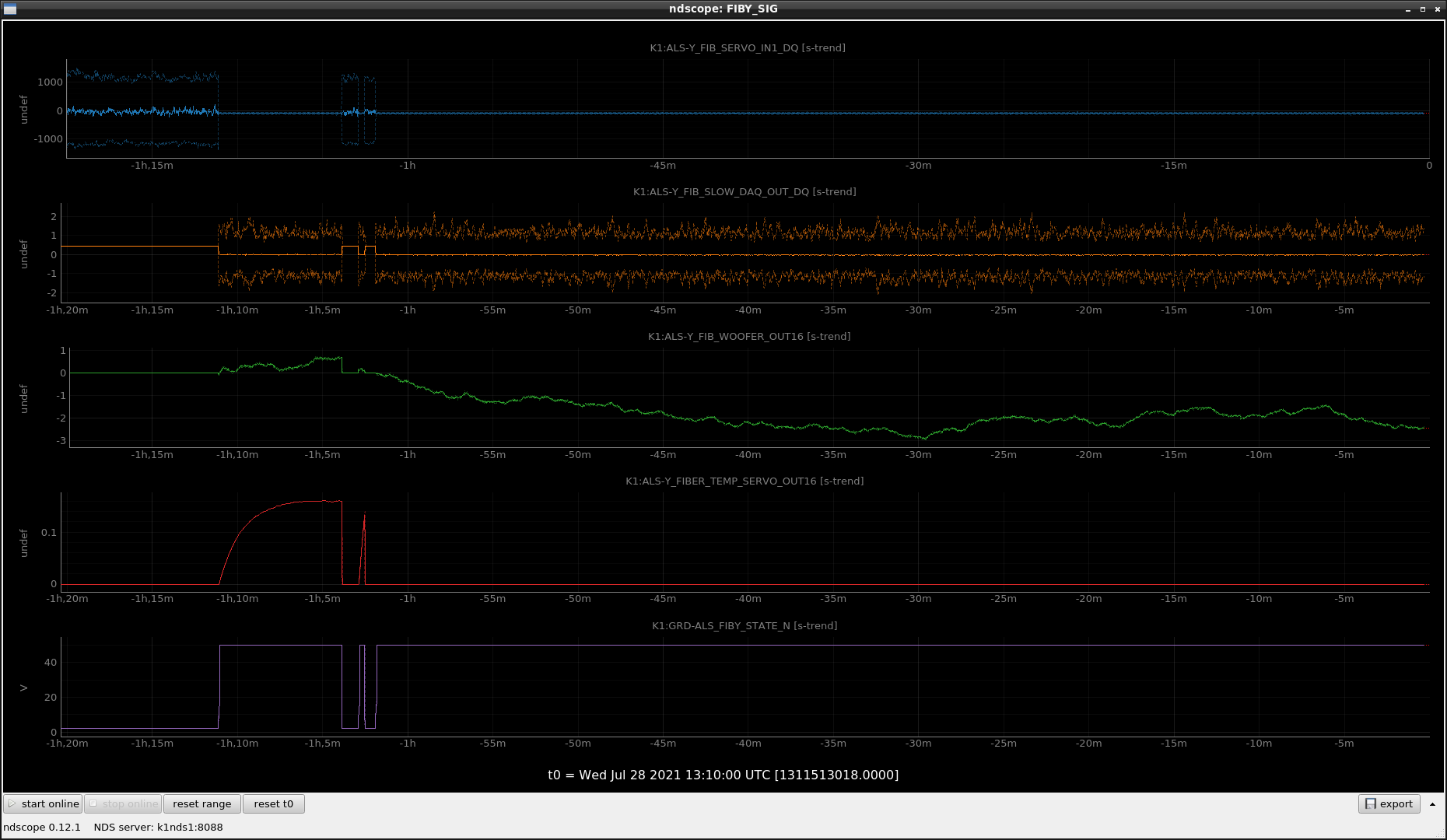
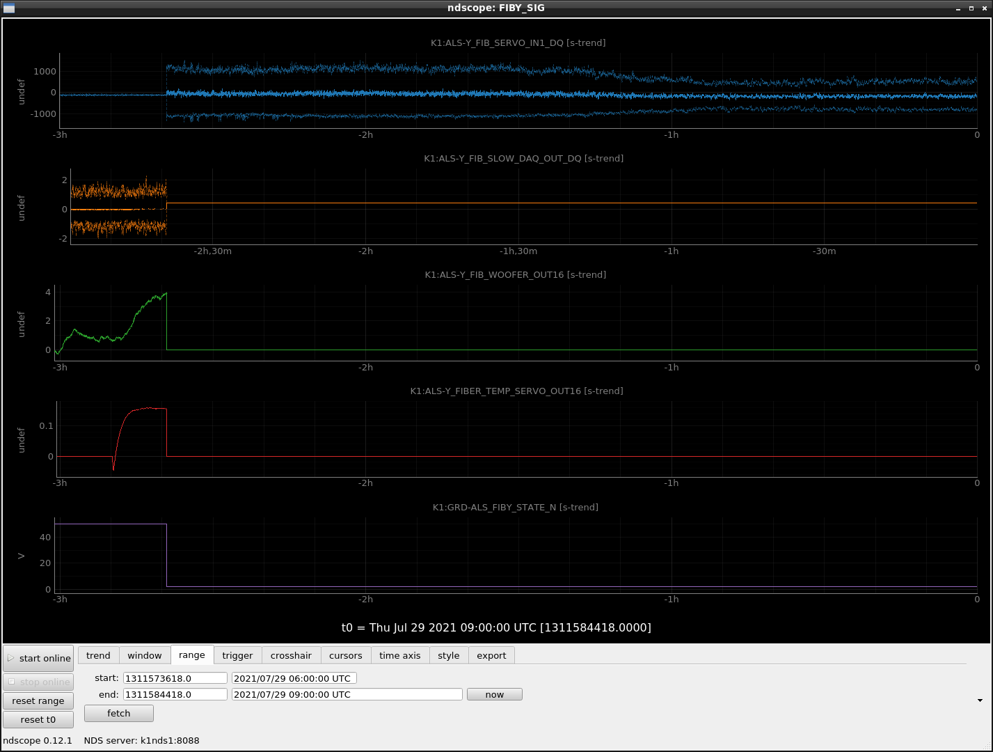
Fig.2 shows control signals during lock.
At first, I tried to lock with heater feedback same as past trial (from -1h10m to -1h5m). This is just a quick check that FNC can be locked same as past.
After then (from around -1h), FNC was locked again without heater feedback.
(Very short lock around -1h3m is my mistake that I turned off only the input switch and forgot to turn off the offset switch...)

Abstract
In order to remove NIM module from ASC0 rack, we checked lock scheme without the heater feedback again.
As the result, we found the evidence that heater control may not be able to be turned off.
So today, we postponed the removal of NIM module.
Detailed
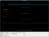
At first we found the fringe became smaller (~1000ct p2p) than the nominal (~2000ct p2p).
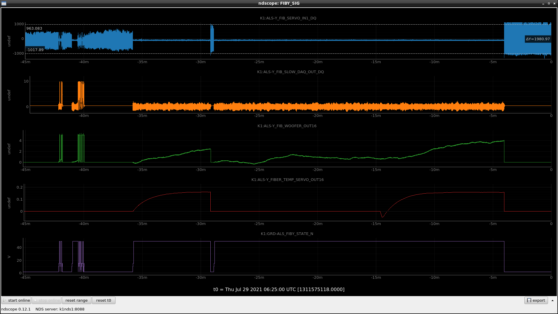
Under this situation, FNC-Y lock was lost again and again due to the saturation of woofer feedback (around -40m in Fig.1).
Yesterday's midnight I left the FNC with the LOCK state without heater output. So heater output was kept as 0 for a long time.
(In the case of DOWN state, some offset is set for heater output.)
From this fact, we doubted we need the DC offset for heater output though heater feedback is not required.
When we tried to lock FNC-Y with heater output again (from -35m to -30m in Fig.1), it was able to be locked and we kept LOCK state for a while.
After then, when we requested DOWN state once, we was able to find that fringe became roughly nominal value (~2000ct p2p).
Finally, FNC-Y lock was recovered (from -30m to -15m in Fig.1). During lock state, we played a prank that heater output turning.
In order to lock FNC-Y without heater feedback, pre-heating of POS table may be necessary.
In order to confirm reproducibility of fringe amplitude and DC offset of heater output, we left heater output cable was unplugged today.
By checking fringe amplitude after exiting from mine, we was surely able to see the decreasing amplitude shown as Fig.2.
We may need re-alignment without DC heater offset.
Same as PSL room temperature discussion, it may be better to prepare the thermometer for measuring POP/POS table temperature.
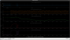
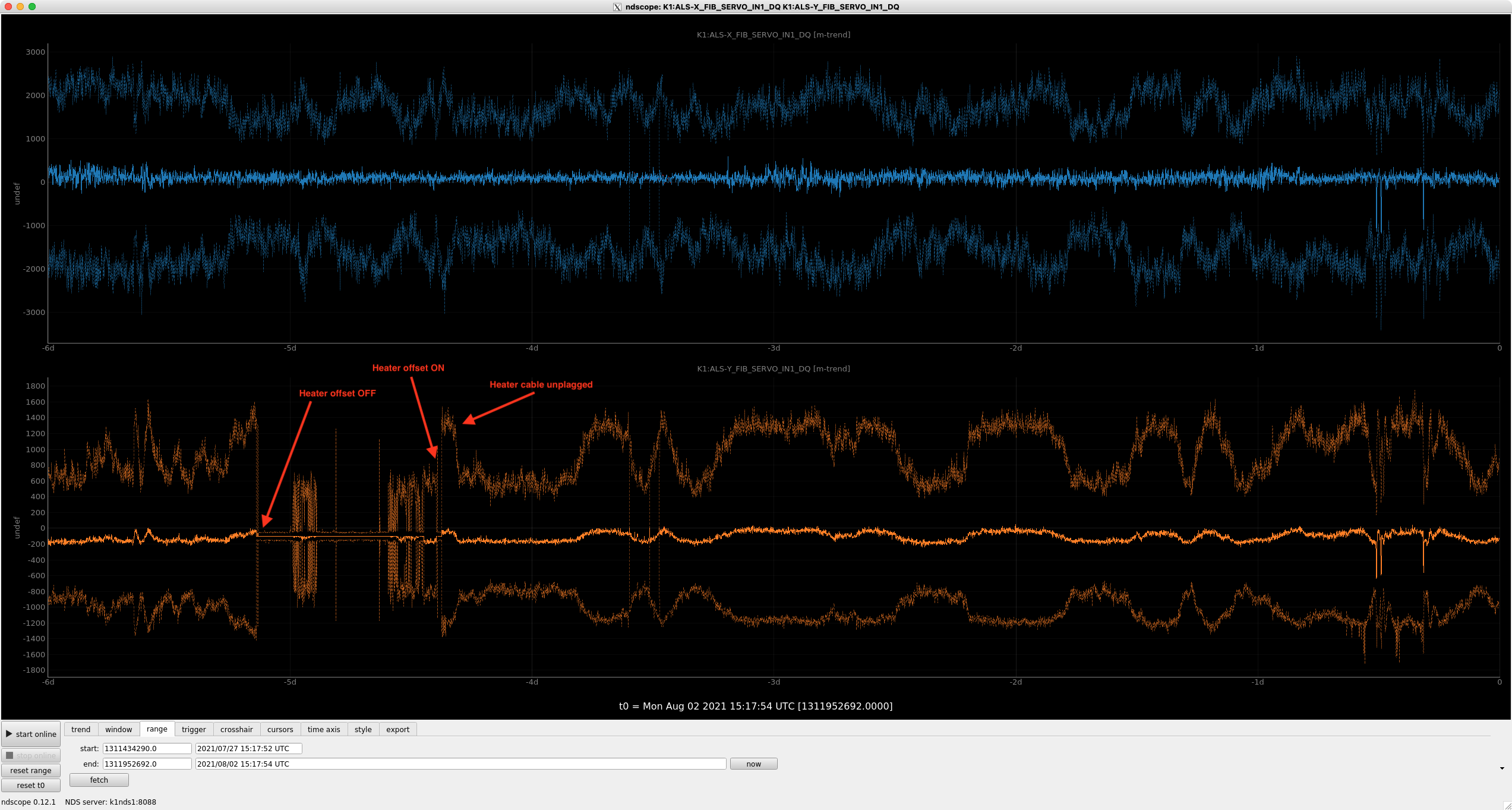
I checked several days data of fringe signals after unplugging the heater output cable. Then amplitude of fringe signals still changes in many times.
Bottom panel of Fig.1 shows that the amplitude still changed after unplugging the heater cable 5 days ago.
In last time, we were able to see the reproducibility of the relation between the heater offset and fringe amplitude.
I'm not sure this result was accidental coincidence or the real relation in a short term. But at least in a long term relation, there seems to be other reason why the amplitude changes.
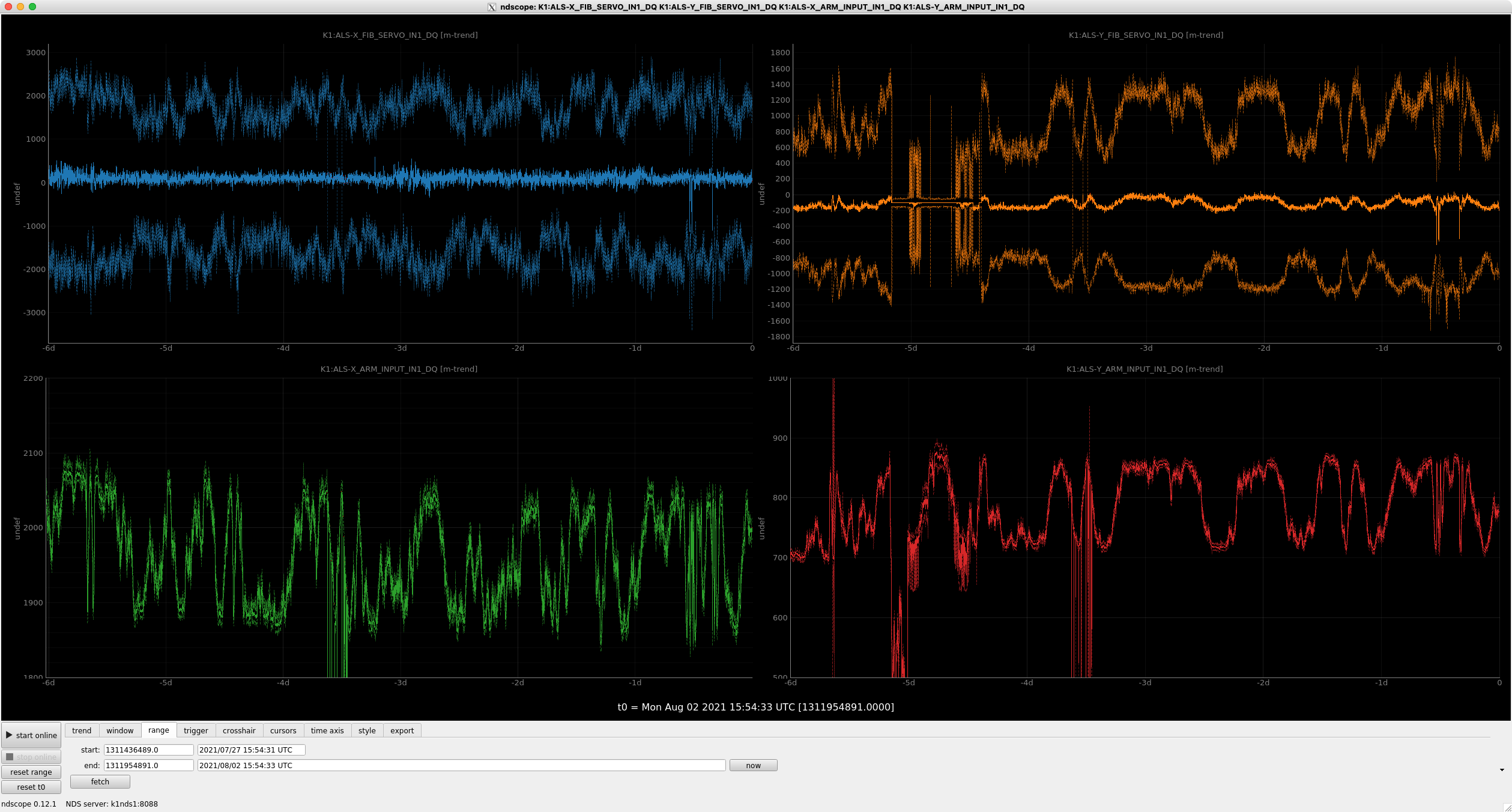
The fiber output PD on the POP/POS tables are ones of the few non-control signal sensors for green laser systems, so I checked also these signals.
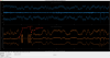
The fiber output power seems to change correlated to the change in fringe amplitude.
Fig.2 shows the fringe amplitude (upper) and the power at POP/POS tables (lower). In both X (left) and Y (right), the correlation can be seen between the fringe amplitude and the laser power at POP/POS.
Does this mean that the change is already occurring at the output laser power from the PSL room, rather than a change in the interference state or the power of return light from the POP/POS tables?
(Fiber coupling in PSL room, output laser power itself from Prometheus, etc.?)