Reports 1-1 of 1 Clear search Modify search
IOO (IMC)
kenta.tanaka - 4:00 Friday 09 July 2021 (17443) Print this report
close the control loops for mirrors of IMC alignment with global sensors

C. Hirose, K. Tanaka 

### Choose DOFs and made DOF sensors 

Based on Hirose'-san s previous sensing matrix results (see klog 17414), we decided on the combination of sensors that are most sensitive to the DoF in each of the MCE, COM and DIF modes between MCI and MCO of YAW direction. The sensing matrix shows that the REFL WFS is equally sensitive to MCE motion and {COM. DIF} modes motion, while the MCE TRANS has greater sensitivity to MCE motion than the other degrees of freedom. Therefore, the motion of the MCE is first detected by MCE TRANS DCQPDs, and then the motion of the MCE is controlled with MCE TRAMS DCQPDs. Then, in its control band of MCE angular motion, the motion of the MCE becomes small, and the REFL WFS can be used to detect the motion of the {COM, DIF} modes. The following is the summary.

YAW

  • DOF1: REFL WFS1 - 0.7675*REFL WFS2 -> COM YAW
  • DOF2; 0.5648*REFL WFS1 + REFL WFS2 -> DIF YAW
  • DOF3: MCE TRANS DCQPD1 + 0.7212*MCE TRANS DCQPD2 -> MCE YAW

### model

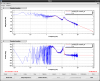
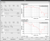
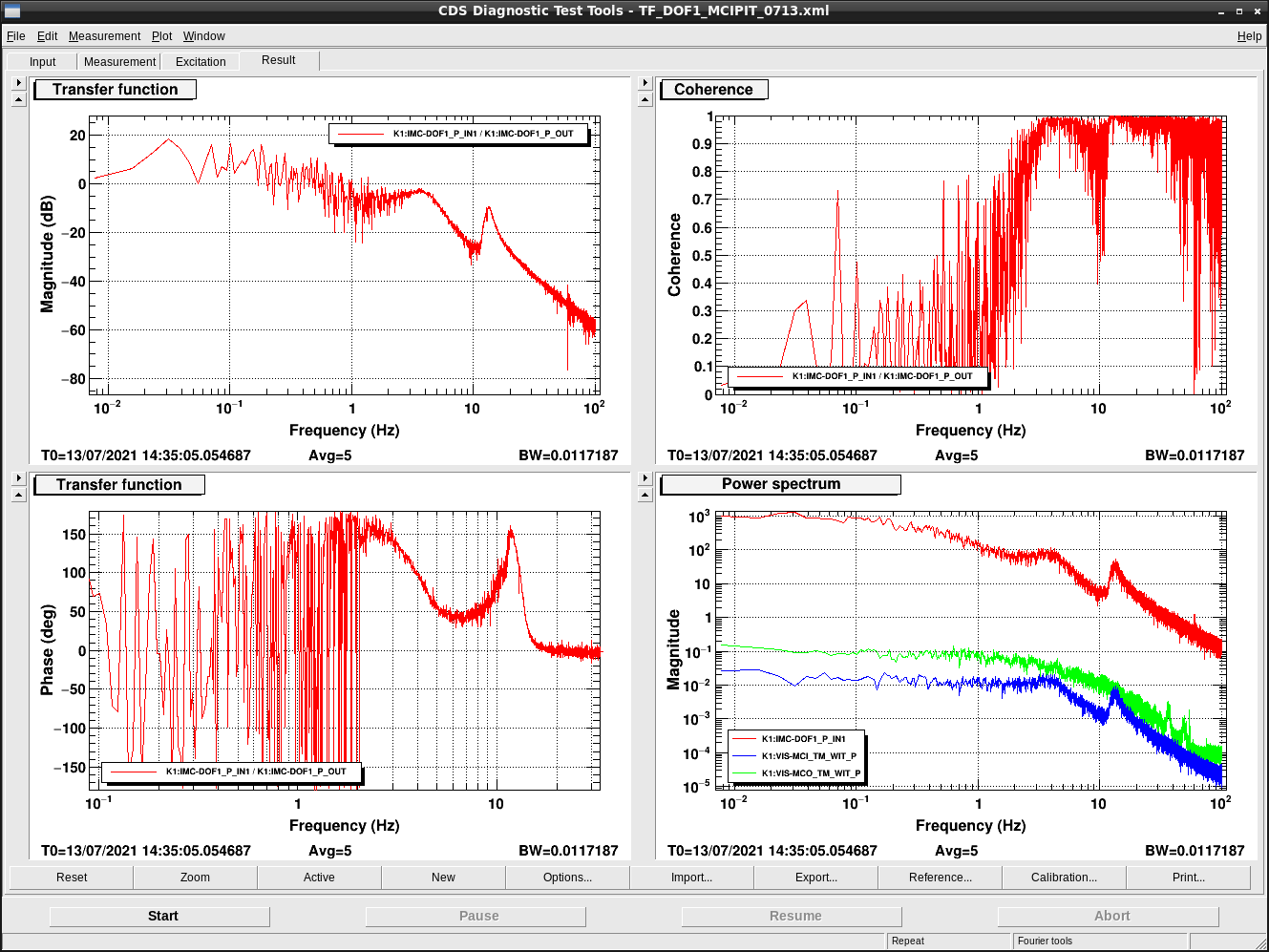
Using the above sensor, the transfer function from A to B was measured by inserting an excitation signal, as shown in Fig. 1. We created a model of the transfer function by using a zpk filter to visually match the measured transfer function. For example, in the case of COMYAW, it was created as shown in Figure 2. The measurement results for the other degrees of freedom are placed in /users/Commissioning/data/IMC/2021/TF_sup

### Open-loop TF

By using the models of the measured transfer functions, we create filters for controlling the MCE YAW, COM YAW, and DIF YAW degrees of freedom. We then closed the control loop for these degrees of freedom. Fig 3, 4, 5 show the OLTFs of MCE YAW, COM YAW and DIF YAW. we summarized each U.G.F and phase margin below a table. Fig 6, 7, 8 show the angular fluctuations in each degree of freedom with and without control, as seen by the in-loop sensor and the oplev.  

Looking at the COM oplev signal, it is louder on the low frequency side than it was before the control was applied. > <

  U.G.F phase margin
MCE YAW 4 Hz 44 deg
COM YAW 3 Hz 22 deg
DIF YAW 3 Hz 25 deg


Images attached to this report
Comments to this report:
kenta.tanaka - 2:12 Tuesday 13 July 2021 (17487) Print this report

### YAW

We further combined the previous DOF sensors to create sensors that are sensitive to each of COM, DIF, and MCE respectively.

YAW

  • DOF3: MCE TRANS DCQPD1 + 0.7212*MCE TRANS DCQPD2 -> MCE YAW
  • DOF1: REFL WFS1 - 0.7675*REFL WFS2 - 6689*DOF3  -> COM YAW
  • DOF2: 0.5648*REFL WFS1 + REFL WFS2 - 5251*DOF3 -> DIF YAW

This allows the UGF of the com/dif mode loop to be determined independently of the UGF of the MCE loop. Using these sensors, we closed the loop controlling each of the COM/DIF/MCE.

FIG1. 2, 3 show OLTFs of each MCE, COM, DIF in yaw direction.

And we measured the spectra with K1:IMC-DOF{1, 2, 3}_IN1 as in-loop sensors, K1:IMC-IMMT1_TRANS_QPDA1_DC_YAW_OUT, Length signal (K1:IMC-MCL_SERVO_IN1) and OPLEV (K1:VIS-MC{I, O, E}_TM_WIT_Y) as out-loop sensor, Fig. 4, 5, 6 show these results. blue line: all 3 DoFs are not controlled, brown lines: only one DoF is controlled without boost, black lines : only one DoF is controlled with boost, red lines : all three DoFs are controlled. When MCE loop closed, There is no change in the out-loop sensor. Otherwise, when COM/DIF loops closed, On the low frequency side of K1:IMC-IMMT1_TRANS_QPDA1_DC_YAW_OUT and oplev sensor signals, the signals has increased. This is thought to be due to the fact that the WFS noise is being returned, causing the mirror to shake excessively in this band. Figure 7 shows the time series data of the in-loop sensor and IMMT TRANS signals when the COM loop is closed. It can be seen that the RMS of the in-loop sensor becomes smaller as the control is applied, but the signal of IMMT1 TRANS becomes larger.


Images attached to this comment
kouseki.miyo - 9:37 Tuesday 13 July 2021 (17490) Print this report

I reverted MCI_TM_DRIVEALIGN_P2L_GAIN as shown in attached figure because Tanaka-kun said that it was changed accidentatly.

Images attached to this comment
kenta.tanaka - 2:50 Wednesday 14 July 2021 (17507) Print this report

### PIT

We continued to work on the control of the PIT.
First, we created the DOF sensor as well as the YAW.

  • DOF3 : 0.29613*MCE TRANS DCQPD1 + MCE TRANS DCQPD2 -> MCE PIT
  • DOF1 : WFS1 - 4.0210*WFS2 +27443*DOF3 -> MCI PIT
  • DOF2 : 1.564*WFS1 + WFS2 -23651*DOF3 -> MCO PIT

We then tried to control the PIT using these sensors. However, the MCE and MCO were able to close the control loop successfully, but the MCI was not able to close the loop. (Hirose-san will post the details later.)

Figures 1 and 2 show the respective open-loop transfer functions of MCE and MCO. Figures 3 and 4 show the spectra of the error signals of IMMT1 TRANS DCQPD and OPLEV, MCL as in-loop and out-loop sensors before (blue lines) and after(red lines) closing the loop.


Images attached to this comment
hirose.chiaki - 3:07 Wednesday 14 July 2021 (17508) Print this report

I made an angle control filter from DOF1_P to MCI_pitch, but it oscillated. (I have stopped it now)
I set the filter to UGF15Hz, phase margin 66deg.
The filter is a lead filter (pole 60Hz, zero1Hz) + gain(0.6) + roll-off filter(100Hz) + gain(-1).
After adding the control filter, it oscillated at 2Hz.
The phase of 2Hz is 44deg in the expected open room transfer function.
I have no idea why it oscillates.

Images attached to this comment
Search Help
×

Warning

×