Akutsu, T. Yamamoto, K. Tanaka
We found that there is a switch that selects the pole gain only for the DCQPD. When we compensated for this, we succeeded in eliminating the strange phase rotation.
## swept sine measurement to investigate frequency dependency of phase difference
To investigate the frequency dependence of the phase difference, we swept the frequency from 100 Hz to 1 Hz and measured the transfer function from K1:IMC-DOF3_P_EXC to (K1:IMC_REFL QPDA{1,2}_RF14_I_PIT_OUT, K1:IMC_{MCE, IMMT1}_TRANS_QPDA{1,2}_DC_PIT_OUT). Figure 1 shows the results. First, you can see that there is a peak at about 15Hz. This is thought to be the resonance frequency of the pitch of the MCi. This peak is also seen in the transfer function of P2P that Miyo-san measured in the past. Next, looking at the phase transfer function between the excitation signal and K1:IMC_REFL QPDA{1,2}_RF14_I_PIT_OUT_DQ, we can see that the phase transfer function is 0 or 180 degrees at higher frequencies than 15 Hz. (At frequencies lower than 10 Hz, the RFQPD loses coherence because the amplitude of the excitation signal is reduced not to be down IMC lock. (Fig. 2)). On the other hand, the phase transfer functions of K1:IMC_{MCE, IMMT1}_TRANS_QPDA{1,2}_DC_PIT_OUT/K1:IMC-DOF3_P_EXC and K1:VIS-MCI_TM_WIT_P/K1:IMC-DOF3_P_EXC show that these phases continue to rotate. Figure 3 shows the phase transfer function of K1:IMC_{MCE, IMMT1}_TRANS_QPDA{1,2}_DC_PIT_OUT/K1:VIS-MCI_TM_WIT_P. In each case, the phase is lifted at the high-frequency side.
## Checking the DCQPD circuit
We checked the circuit of the DCQPD for ASC and the QPD used in the oplev. According to this diagram, the QPD has a gain switch that allows the user to select between a gain with a 16 Hz pole and a gain with an 80 Hz pole. Figure 4 shows these Bode diagrams. As you can see, the gain with a 16Hz pole turns the phase by 50 degrees at 20Hz. On the other hand, the gain with an 80 Hz pole has a phase rotation of 15 degrees at 20 Hz. These values are consistent with the results in the previous Table 2. Based on this, we expected the 16 Hz pole gain to be in the DCQPDs and the 80 Hz pole gain to be in the OPLEV. Since this gain switch does not exist in the RFQPD, it explains why there is no phase shift in the RFQPD and only the DCQPD shows phase shift. We then multiplied K1:IMC_{MCE, IMMT1}_TRANS_QPDA{1,2}_DC_PIT_OUT by a filter with zeros that compensate for the 16 Hz pole, and the OPLEV QPD signal by a filter with zeros that compensate for the 80 Hz pole. Figure 5 shows the phase transfer function after multiplication. As can be seen, all the phase transfer functions are zero and 180 degrees.
## Test this hypothesis of QPD gain switch
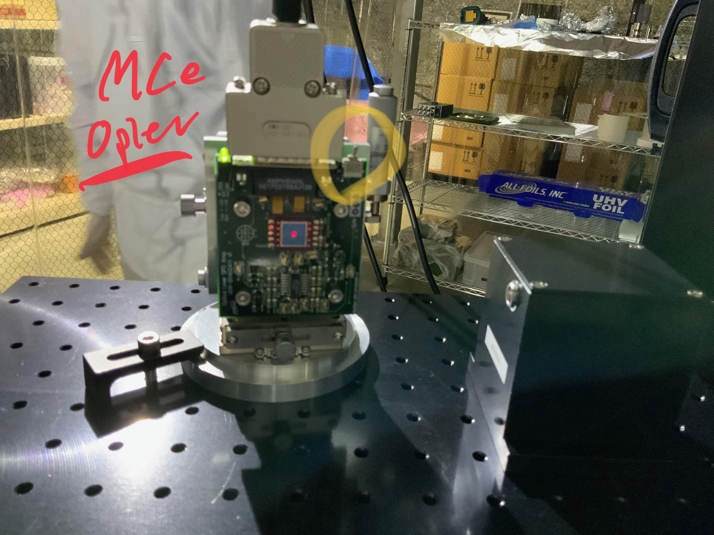
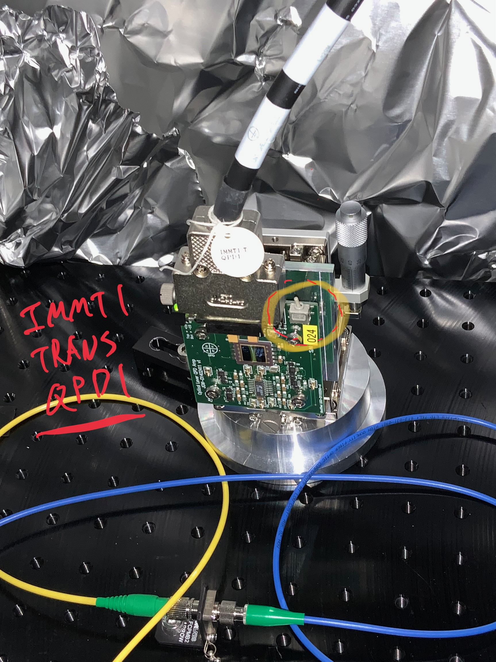
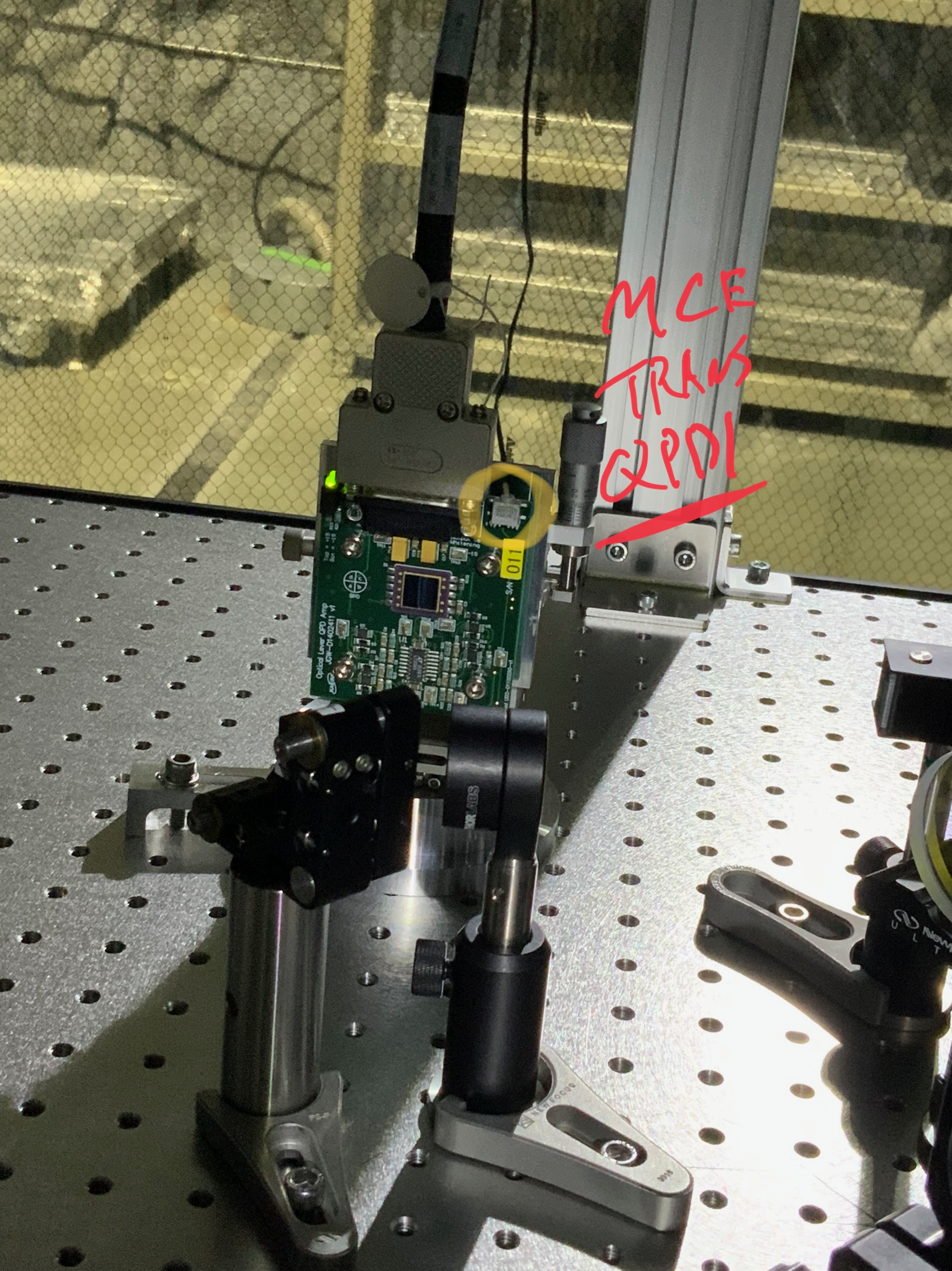
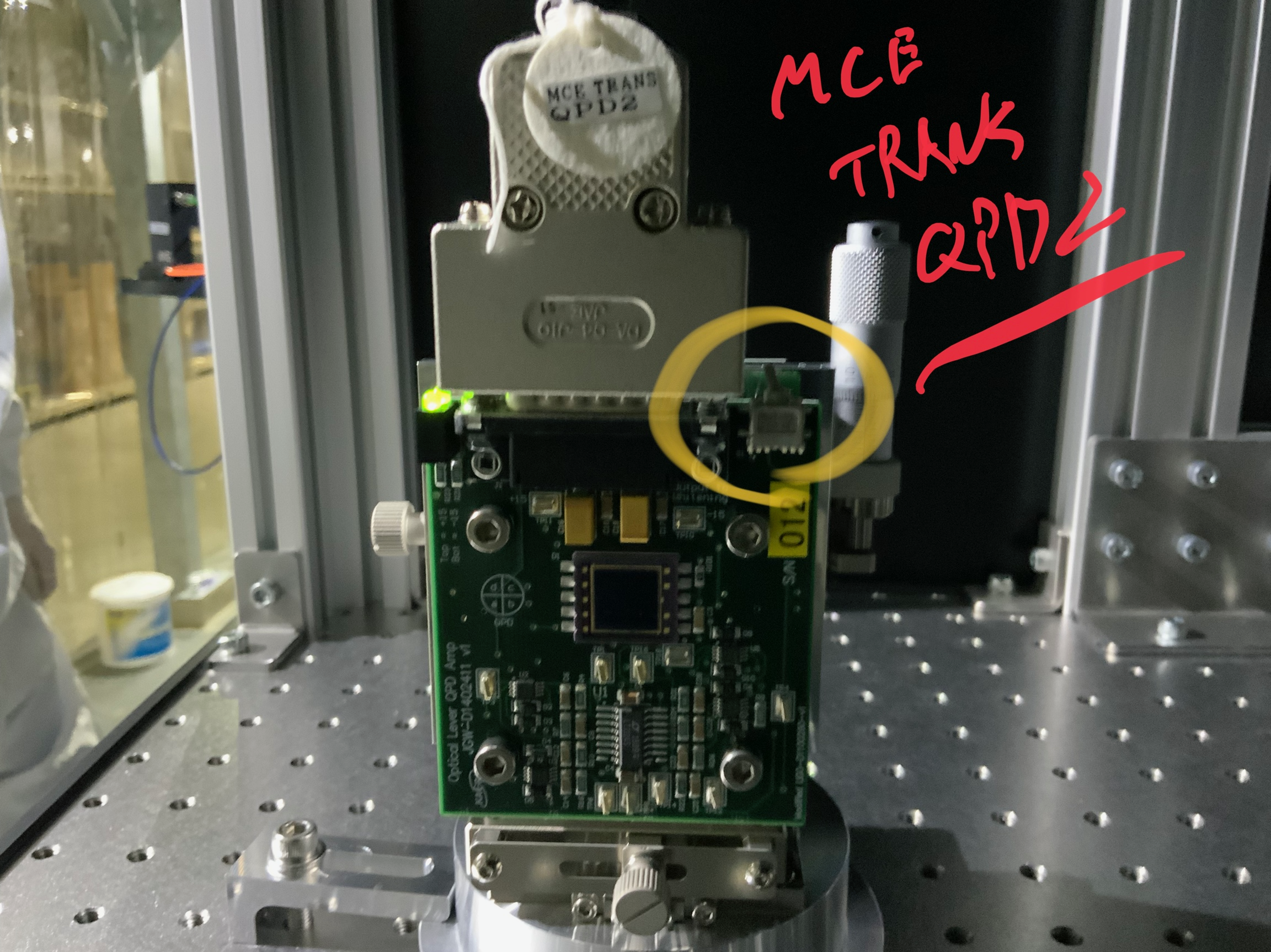
We actually went into the mine to check which gain switch was selected for each QPD. Figs. 6, 7, and 8 are pictures of the IMC suspension oplev. Figures 9, 10, and 11 are photos of MCE TRANS QPD1, QPD2, and IMMT1 TRANS QPD, respectively. The following table summarizes the orientation of the switches when the QPD is viewed from the front.
| toggled direction from the view of QPD front | toggled direction from the view of QPD front | ||
| MCI oplev | right | MCE TRANS QPD1 | left |
| MCO oplev | right | MCE TRANS QPD2 | left |
| MCE oplev | right | IMMT1 TRANS QPD1 | left |
The switch direction of the DCQPD is different from the switch direction of the Oplev.
Next, I checked which direction had which gain by seeing how the magnitude of K1:IMC-IMMT1_TRANS_QPDA1_DC_SUM_OUT_DQ changed when I moved the toggle switch of the IMMT1 QPD. The result is shown in Fig. 12. According to the circuit diagram, the 16Hz pole gain is five times larger than the 80Hz pole gain. From this point of view, the signal when the toggle is facing left is five times larger than the signal when the toggle is facing right. In other words, when the toggle is facing left, the gain is 16 Hz pole gain, and when it is facing right, the gain is 80 Hz pole gain. This is consistent with the above hypothesis.


.png)
.png)


.png)
.png)