Continue work in 17137.
It wasn't easy to obtain a reasonable L-T coupling ratios at the resonances since the modes are L-T coupled.
I reverted the LVDT2EUL and EUL2COIL matrices back to the geometric one derived by Mark a long time ago and the results are pretty much the same.
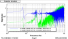
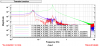
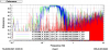
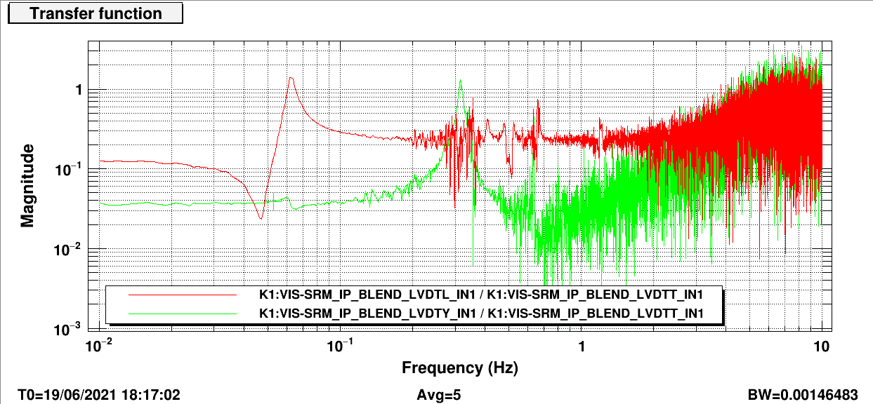
But, plotting L/T and T/L "transfer functions" yielded interesting properties, i.e. the two transfer functions are mostly flat above 0.1 Hz, (roughly) equal in magnitude (~0.23) but with opposite sign (0 and 180 degrees). See Fig. 1 and 2.
These symptoms are consistent with a rotational transformation. And it makes sense as sensor cross-coupling would show the same spectrum shape to another channel.
Measuring the coupling ratios between Y and L/T are relatively straightforward but required several iterations, as L and T resonances overlap.
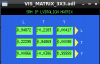
At the end, I arrived at an LVDTALIGN matrix as shown in Fig. 3.
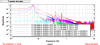
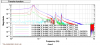
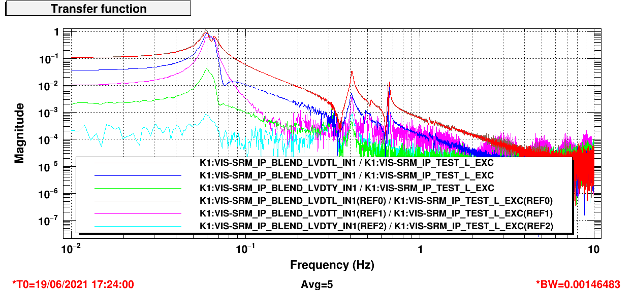
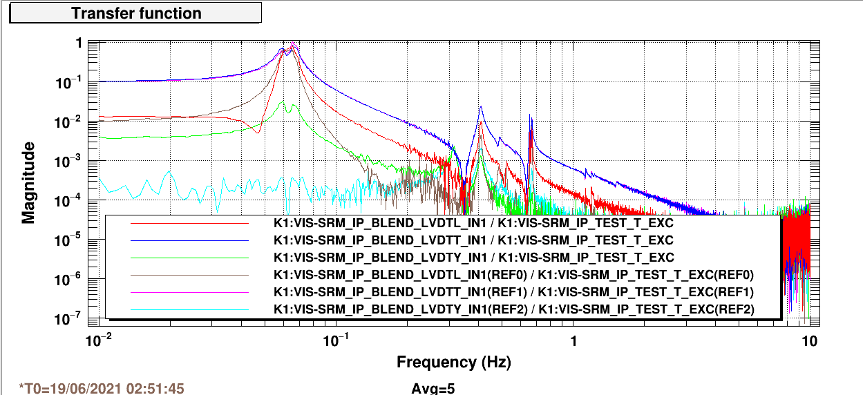
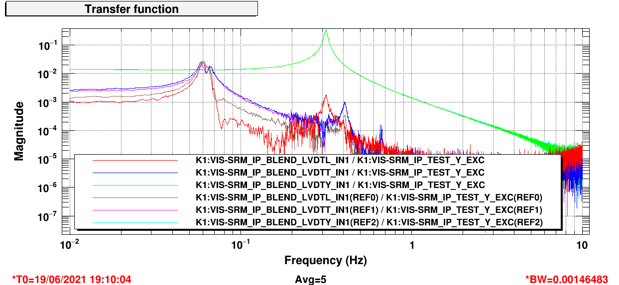
I then compared the transfer functions before and after applying the LVDTALIGN matrix. These are shown in Fig. 4, 5, and 6. References plots are those with the new LVDTALIGN matrix.
As can be seen, L/T coupling receives a significant amount of broadband reduction while Y to L/T and L/T to Y has minimal coupling at resonances.
There's a caveat. There's a chance that by applying the new LVDTALIGN matrix, we rotated the sensor frame to the actuation frame, but not necessarily the true L/T.
However, this cannot be confirmed, and I am satisfied with the results so I will just leave it this way.
For a sanity check, I measured the L/T free swing spectra and compare them with the seismometer x/y spectra. They should give evidence of whether or not the sensors are well aligned to the interferometer X/Y.
The coherence between the four channels are shown in Fig. 7. As expected, around the microseism frequencies (very large microseism today, peaked at 1 um/sqrt(Hz) during measurement, good for this measurement), L is correlated to seismometer y, but not x, and T is correlated to seismometer x, but not y.
This is very good evidence that L and T are readouts are truely L and T.
Nevertheless, the resonance frequencies as measured in diaggui for the L/T modes are roughly 59.8 mHz and 66.7mHz
All measurements are custom files that are located in /kagra/Dropbox/Personal/Terrence/vis_commissioning/srm/. I put them there so I have convenient remote access.
Next steps would be to align and intercalibrate the geophones and seismometers for blending and sensor correction. I might do actuation diagonalization, but I don't think it's that important.
BTW, the OpLev signals are zeroed out. Is there an optical lever installed for SRM? This will become very important very soon as I go into control tuning, even for the IP.
Additionally, can we have a sensor correction path for the optical levers? With this path, we'd be able to measure the actual control performance of the suspension as an out-of-loop sensor.
Without that, the optical levers will be covered seismic noise and it'd be very suboptimal. It'd be difficult to utilize the optical levers for local controls when the seismic noise level is high as well.
