Method
For an actuator coupled system, displacement reads
,
where is the coupling matrix with diagonal elements being the actuation efficiencies and off-diagonal elements being coupling ratios, and
is the actuation signal.
The coupling matrix is a product of the actuation matrix (software) and mechanical coupling matrix, i.e. .
It follows that
is a diagonal matrix with the same actuation efficiency.
Therefore, if we modify the sensing matrix
,
then the actuators are diagonalized.
Results
for , i.e. (longitudinal displacement, pitch, yaw),
,
, i.e. (longitudinal actuation, pitch actuation, yaw actuation).
I measured coupling matrix
.
Here, the first row is for longitudinal coupling. But there's no length sensor so I just set it to (1, 0, 0). The first number won't matter as long as the others are 0.
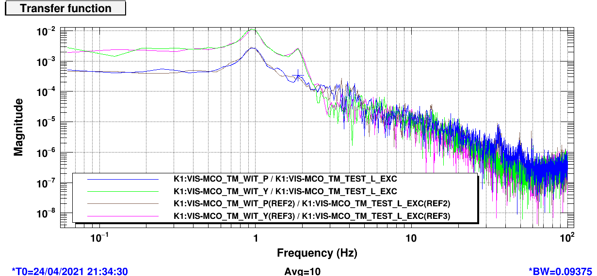
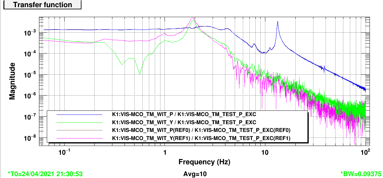
For the second row, i.e. actuation to pitch coupling, the ratios are measured at 14.25 Hz, i.e. injecting L, P, Y line at 14.25 Hz.
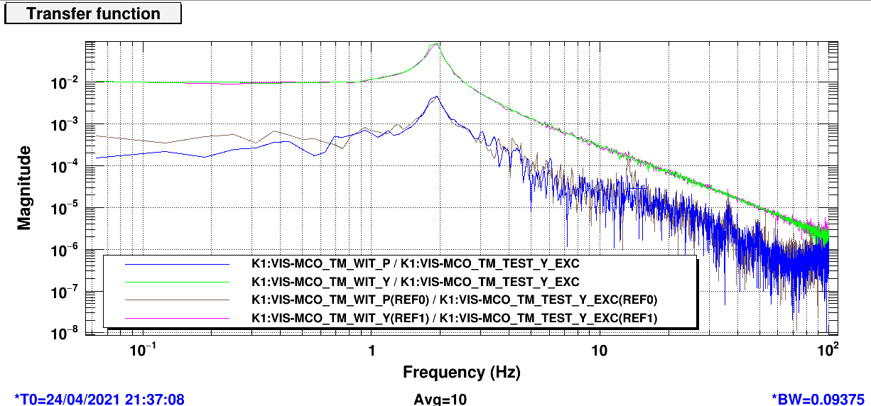
For the third row, i.e. actuation to yaw coupling, the ratios are measured at 0.2 Hz.
These frequencies are chosen such that all coupling ratios have a phase of ~0 or ~180 degrees. This can be judged from the transfer functions and "cross" transfer functions.
For actuation L to Y coupling, it's actually not zero. It's 0.00220762 but with a phase of 152 degrees. I didn't include this simply because the yaw readout is coupled to longitudinal displacement.
Similarly, actuation P to Y coupling is not accurate, but I include it anyway, assuming that the yaw readout reads more yaw than length, and that actuation P2L coupling is small.
This gives a new actuation matrix
.
After applying this new EUL2OSEM matrix, I measured coupling again and got
,
which has much smaller off-diagonal components.
I measured all transfer functions after that. See figures for the transfer functions. Blue and green lines are the transfer functions after actuator diagonalization, and references are the ones before diagonalization.
I modified SDF to save the coefficients.


