Reports 1-1 of 1 Clear search Modify search
VIS (PR2)
fabian.arellano - 19:34 Wednesday 07 April 2021 (16417) Print this report
Tightening of the inner wire locating clamps.

With Hirata-san and Miyo-kun.

See pictures in album PR2 Remedying Work.

We proceeded to tighten all the clamps. We followed these steps:

  • Tightened the weight holding clamps with a 10 Nm torque.
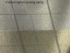
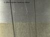
  • At the sides of the RM, underneath the wire breakers, we put spacers between the clamped tungten wires and the RM side faces. The clamp at the +Y side was loose so we tightened a little before inserting the spacer.
  • Removed outer wire locating clamps at the IM.
  • Removed the coil bodies from the RM.
  • Released the mirror from the RM, taking care of moving the stop screws a safe distance from the mirror.
  • Placed the jack underneath the RM (Ref. 16355) and moved it up until it was clearly felt it was about to lift the RM.
  • Then we lifted the RM by 2 mm in 500 um steps until the tension in the tungsten wires had decresed enough to be moved aside at the clamps level. We used the RM lower stop screws to keep it at a suitable horizontal level.
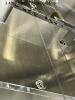
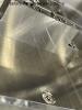
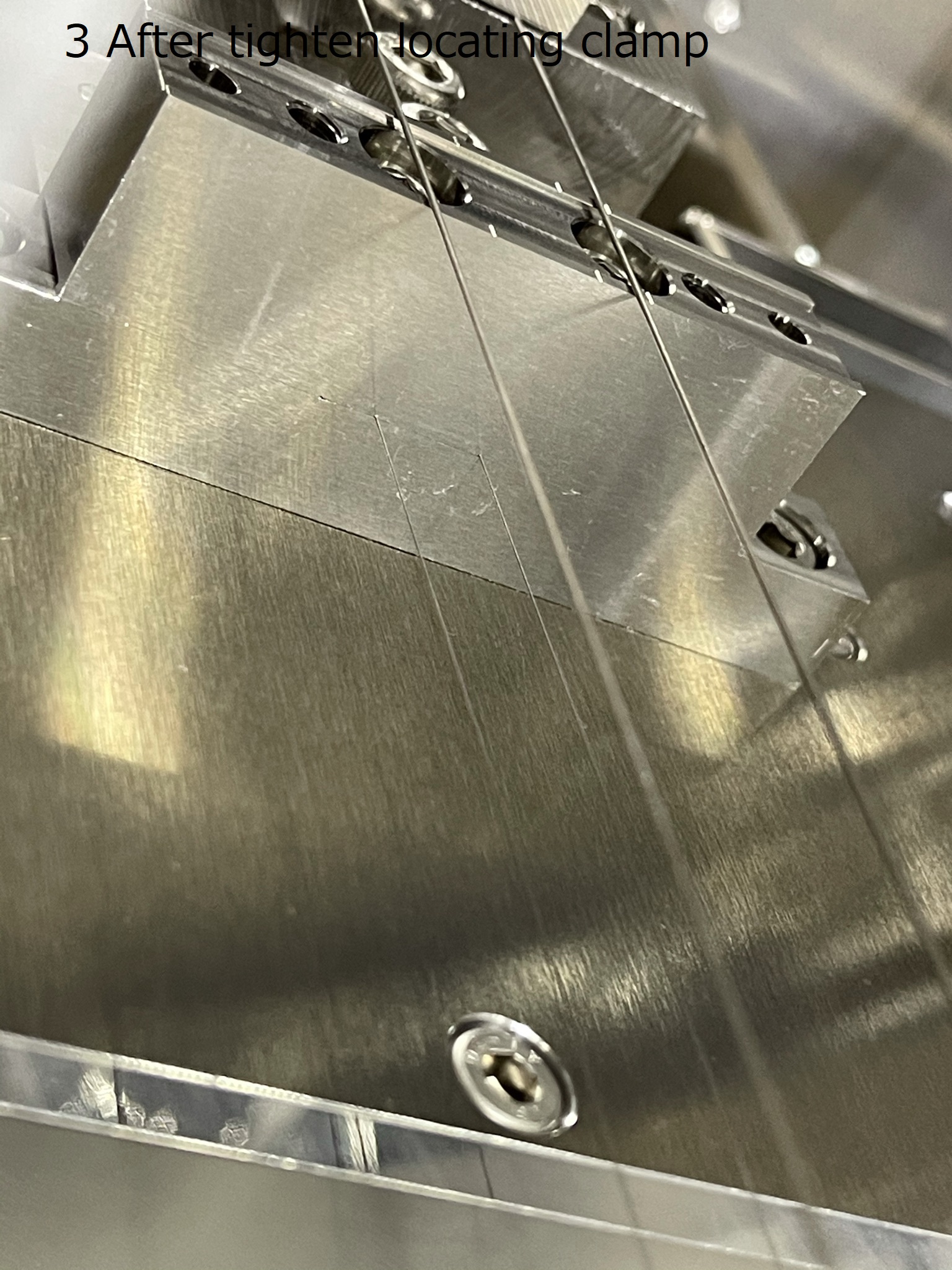
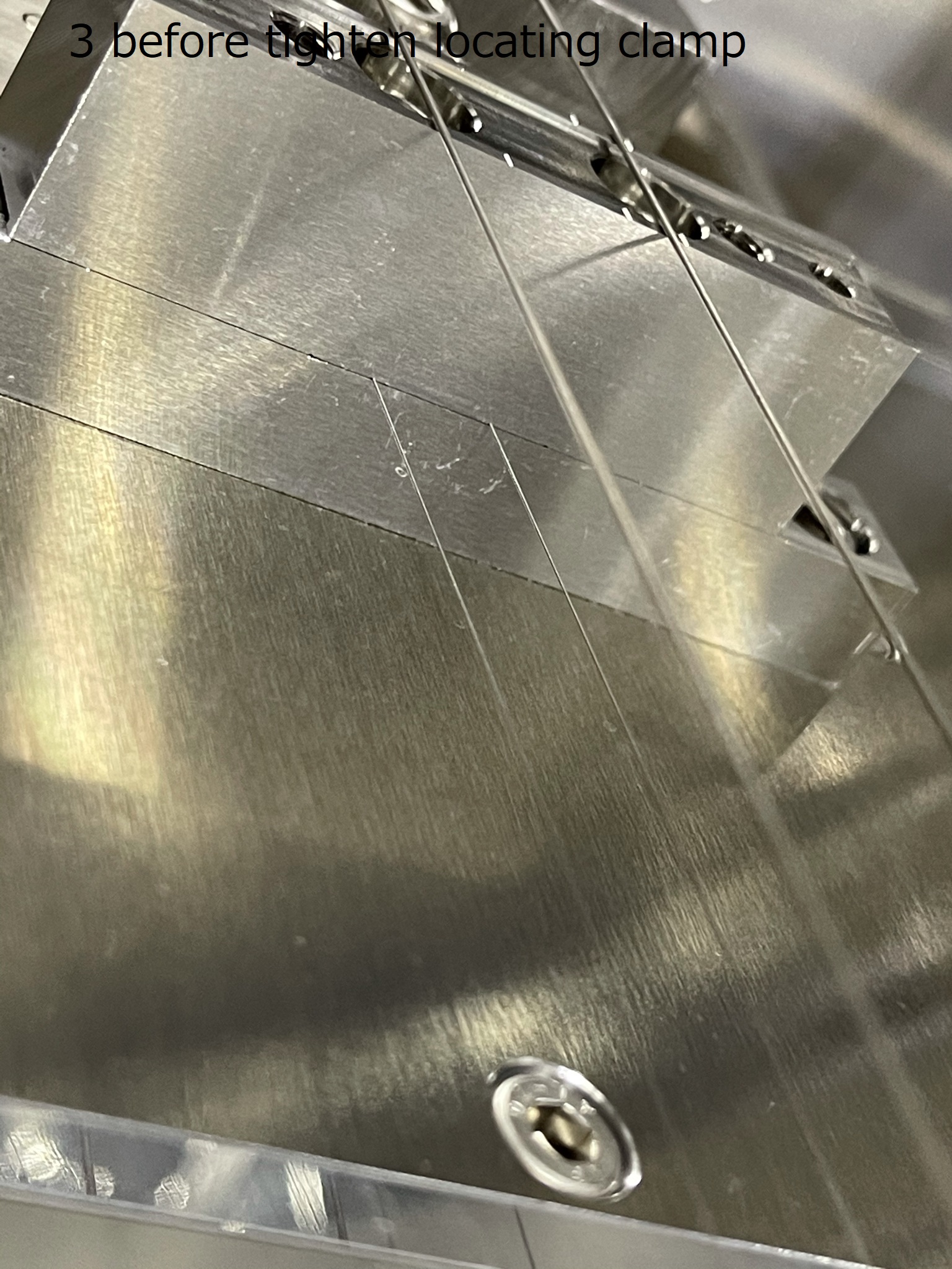
  • We tightened the inner wire locating clamps with a torque of 2 Nm. Highlights:
    • The -Y side was easy because the wires were in the grooves already.
    • However, the +Y side was hard because one wire was not in the groove.
    • The clamps had to be opened a little more to make it easy to put the wire in the grove.
    • The wire was pushed with a PEEK cable tie.
    • Originally, the screws in the +Y clamp were completely loose.
  • We released the mirror from the RM.
  • We lowered the RM and removed the jack.
  • We locked the RM to the security structure and the mirror to the RM.
Images attached to this report
Comments to this report:
tomotada.akutsu - 19:53 Wednesday 07 April 2021 (16418) Print this report

Good job and OMG :(

fabian.arellano - 17:32 Thursday 08 April 2021 (16427) Print this report

With Hirata-san.

Summary: we finished the assembly of the RM and the IRM and released the payload and BF. There seems to be a large amount of positive pitch in the IM according to the position of the OSEM flags. We will aim to correct it with picomotors.

See pictures in album PR2 Remedying Work.

  • We put back onto the RM the coil bodies. We checked that the efective length of the push screws were 8 mm.
  • We removed the spacers (tips of PEEK cable ties) that were in between the RM sides the the clamped wires, just underneath the wire breakers.
  • We released the mirror and the RM to let the RM hang free.
  • We inspected the outer wire clamps that we had removed. See pictures in the album. The scars were more superficial than in PR3 becuase the clamps had not been tightened properly before.
  • We put the outer clamp in place, made sure the tungsten wires were witin the grooves and tightened the screws with a 2 Nm torque.
  • At  the mirror, we took pictures of the magnet standoffs position within their respective cavities. It seems they are roughy at the same place as before but a more detailed comparison would be good.
  • We put magnets on the H2 and H3 OSEM pedestals. North pole out.
  • We put back the IRM side panels.
  • We put the OSEM flags in place and connected the OSEMs.
  • Released the mirror, RM, IM, IRM and BF.
  • According to the position of the OSEM flags there seems to be a lot of positive pitch. We will aim to correct it with the picomotors.
fabian.arellano - 14:26 Friday 09 April 2021 (16440) Print this report

With Hirata-san.

Summary: the payload seems to be hanging free now, but we were unable to measure transfer functions due to a problem likely in the real-time model.

See pictures in album PR2 Remedying Work.

  • We re-assembled and released the payload and realized it had a lot of negative pitch (I wrote positive in the previous klog, sorry) and at least one OSEM flag was touching.
    • We corrected the pitch with the picomotor.
    • We also moved the BF keystone close to nominal position with the fishing rod.
    • Then we corrected IM yaw with the picomotor.
  • We found picomotor cables and stepper motor cables disconnected, so we connected them beofre being able to use them.
  • By the end of today's work the IM seemed to be hanging free.
  • We tried to measure TFs, but it seems the actuation is not going through because of a problem in the real-time model. Miyo-kun and Ikeda-san will take a look.
fabian.arellano - 18:10 Monday 12 April 2021 (16444) Print this report

Summary: transfer function measurements show the payload is healthy.

The real-time model was alright. A feature in the updated model is that in order to actuate at the payload level it is necessary to have the master switch on at the payload and at the tower level also. Maybe, last week the master switch at the tower level was off.

The case is that I was able to measure transfer functions (TFs) of the IM:

  • I measured IM-L, T, Y, P and R (not V because the SF is locked).
  • All TFs show the system is healthy.
  • The files are in the TypeBpData directory in the subdirectory of today.

Later in the day I moved the BF keystone even closer to the setpoint using the fishing rod.


fabian.arellano - 21:41 Tuesday 13 April 2021 (16460) Print this report

With Hirata-san.

Summary:

See pictures in album PR2 Remedying Work.

We shook the suspension three times using the Trump method and measured the change in pitch using the laser level as an optical lever. The change each time was:

The changes are relatively small for a procedure like the Trump method.

We also checked pitch with respect to the horizontal assuming the laser level is horizontal: the pitch is 11 mrad whereas our aim 3.3 mrad! We tried to correct it with the picomotor but the V1 OSEM flag begins touching the  OSEM body. We need to move the OSEM panel.


fabian.arellano - 18:14 Wednesday 14 April 2021 (16469) Print this report

With Hirata-san.

Summary: The payload looks healthy according to IM transfer functions and the mirror pitch is at nominal value of 3.3 mrad.

See pictures in album PR2 Remedying Work.

  • After we measured the deviation from the horizontal of two laser levels (klog 16465), we used the good one (Tajima Zero) to measure the pitch of the mirror.
  • It was 5 mrad, which is more reasonable than the value we measured with the broken laser level (see entry 16460).
  • We used the picomotor to bring the pitch to 3.3 mrad, which is the nominal value.
  • OSEMs V3 and H3 were out of range; we locked the IRM and moved them into range.
  • We removed the plastic cover from the SF, released the keystone and closed the chamber.
  • We measured IM transfer function from the office: they all are fine, including IM-V.
fabian.arellano - 20:31 Thursday 15 April 2021 (16484) Print this report

With Hirata-san.

See pictures in album PR2 Remedying Work.

Today we inspected the OSEMs. We wantes to make sure none of the flags were close to touching the OSEM bodies.

  • We locked the IRM only and moved V3 and V2 OSEM panels to give more space to the flags.
  • We released the payload and measured the pitch again using the good laser level as an oplev. It was 1.2 mrad although it was supposed to be 3.3 mrad. Maybe our improvised oplev has a large uncertainty or we may have done a mistake. I'll keep watching the suspension.
  • We set pitch to 3.3 mrad using the picomotor.
  • We measured a couple of transfer functions and they were fine.
Search Help
×

Warning

×