[Hirose, K.Tanaka, Nakano]
We aligned the IMC to check the beam position on the MC mirrors. We have aligned and now the beam is on the center for all of the mirror.
- We found that the beam position on the MCo was shifted in yaw during the O3 commissioning. So we open the chamber and align them and check the beam position.
- We wanted to rotate the beam polarization from s to p to avoid buring the mirrors with high intra cavity power. I put HWP just after the beam shutter in the PSL. I rotated it by using the MCREFL DC PD as the reference. We have PBS on the MC REFL table, so if the REFL DC is lowest, the polarization of the injection beam into the IMC is p-pol.
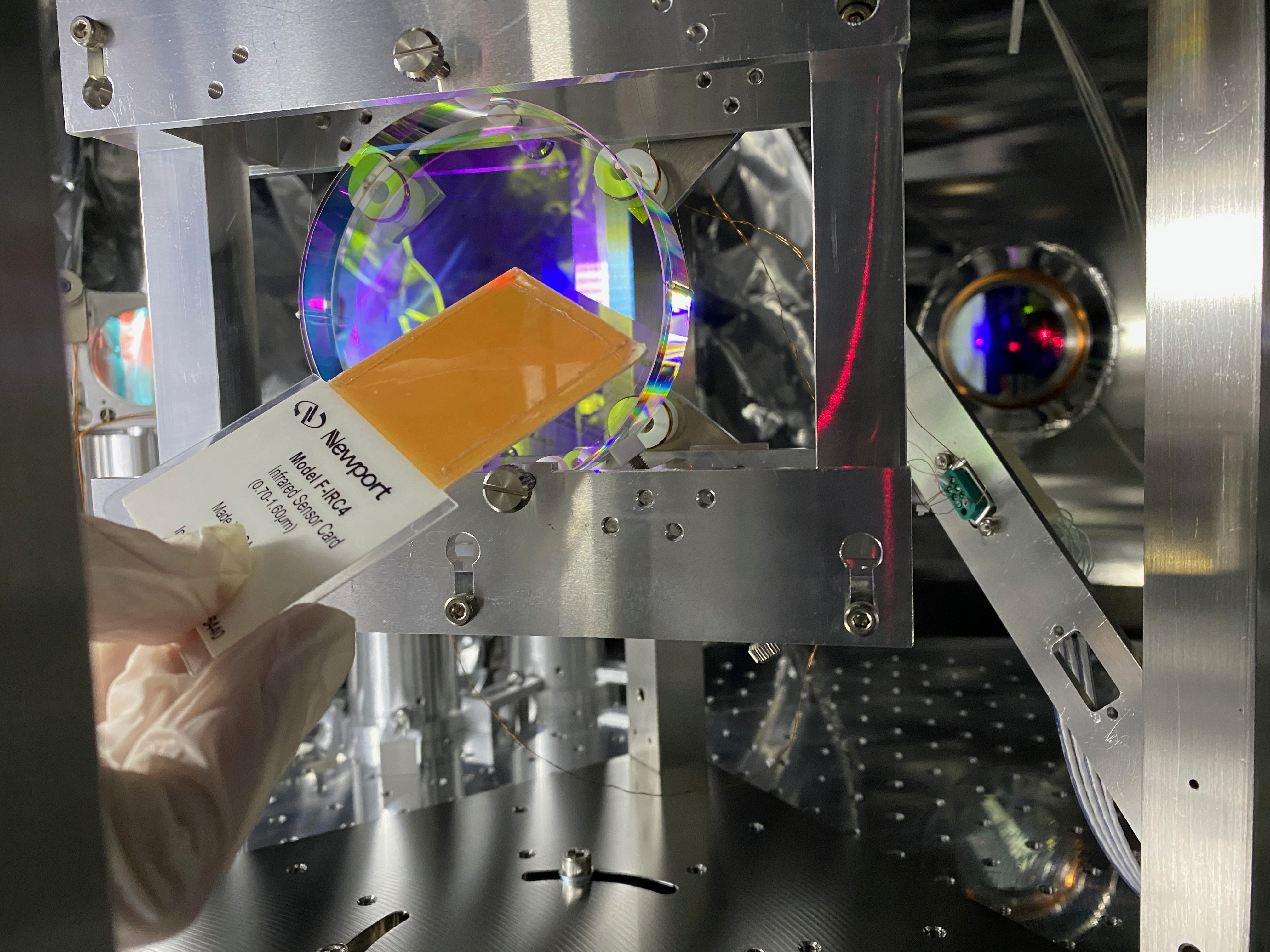
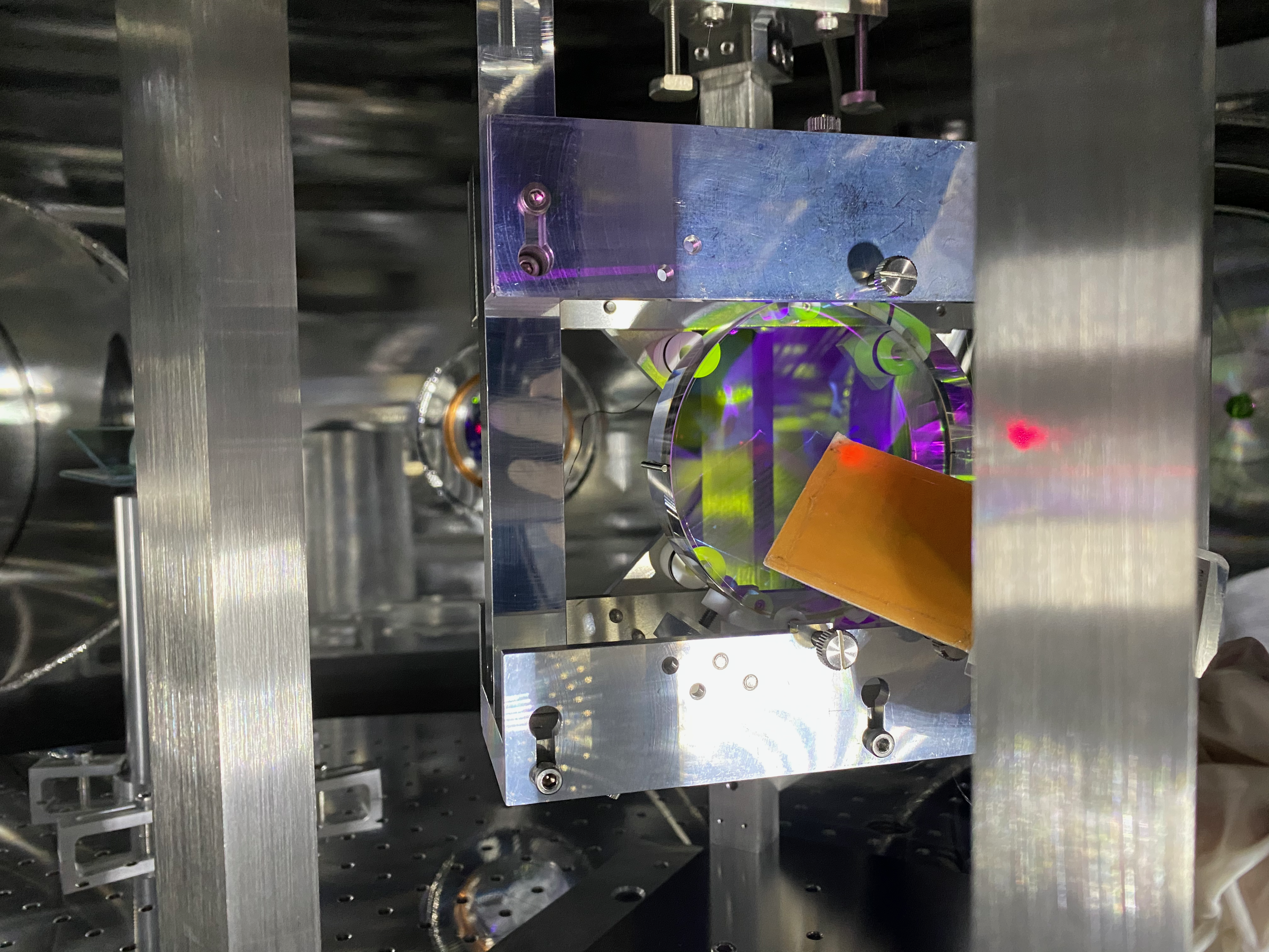
- The reflectivity of MCi and MCo is lower now, so we can see the just transmission light from MCi and MCo. We checked the beam position on the MCi, MCo and STM1, then we found that the beam is shifted in -Y direction by a couple of cm's on the all of the threes.
- We moved the last mirror in the PSL so that the beam hit the center of the STM1, and then the beam hits center of MCi and MCo too. We concluded the reason why the beam shifted on the MCo is that we moved injection axis into the IMC too much. We should make good reference of the output beam pointing.
- We aligned the IMC. First, we aligned MCo and overlap the first round beam and second round beam between MCo and MCe. Here we moved the MCo by rotating the pico by my hands. Then, we put a sensor card on the gate valve, and overlap the first round and second round by tweaking the MCe. At this point, we got good flash and we proceeded the usual alignment procedure.
- We should stop the KOACH during alignment work, otherwise the mirror moved too much.
- We centered all of the oplevs.
- We found one ghost beam between MCi and MCo.

