[Supper miracle great fantastic cabler YOKOZAWA, Nakano]
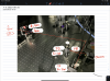
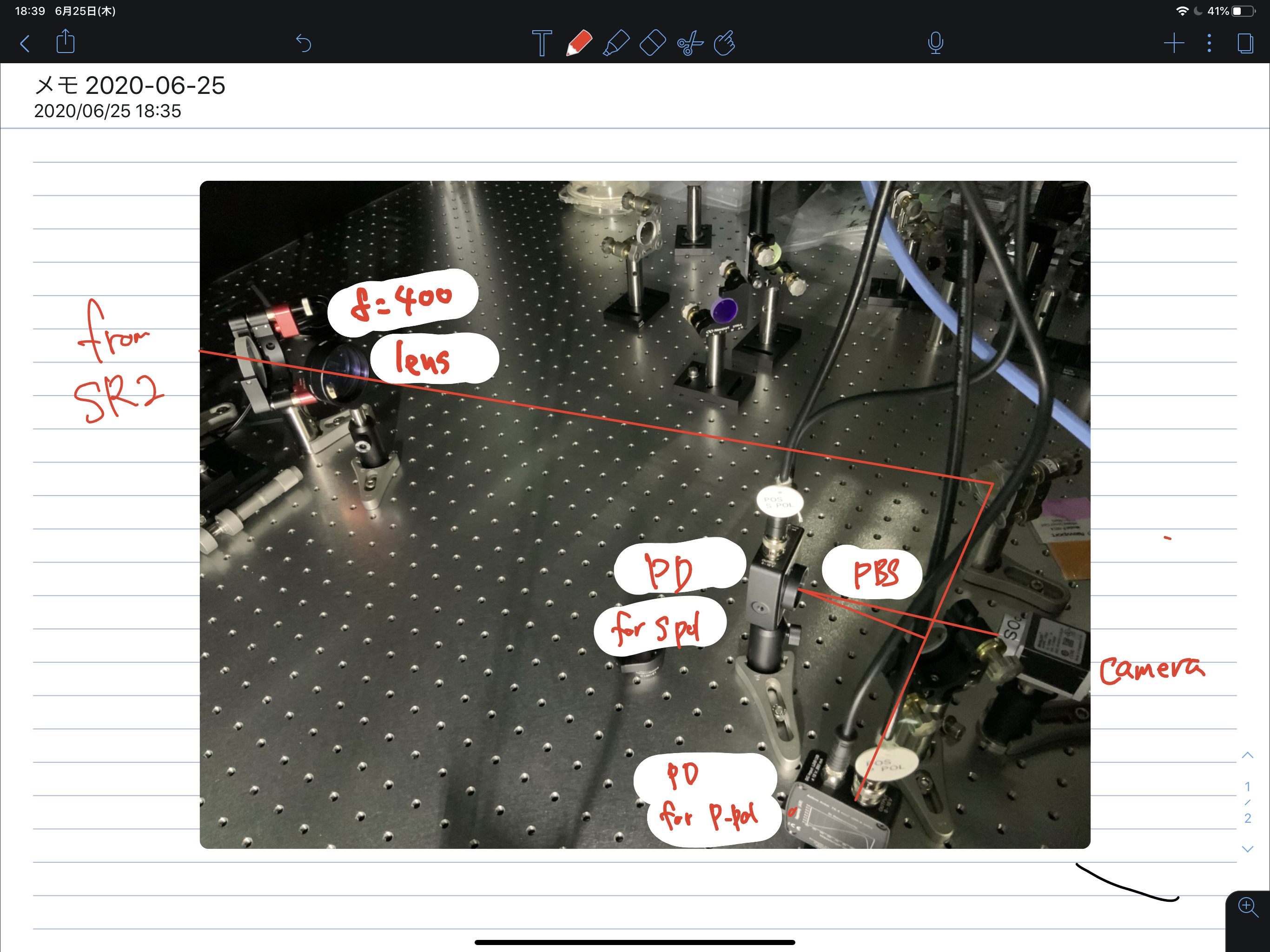
To measure the cavity loss and Lawrence effect, we put the DC PDs (PDA100 of thorlabs). The layout of the POS table is shown in the attached figure.
- The gain of PDA100As are set to 40 dB.
- POS camera image is now different from before. Now the reflection light from the PD is used.
Eventually, we will compare the power of P-pol and S-pol with and without cavity locking. Therefore, it is better to know the transimpedance ratio between two PDs. The measurement procedure is as follows:
- Let me name PD as #1 for s-pol and #2 for p-pol.
- Misalign TMs except for ITMX, and put the single bounse beam on POS into #1 PD.
- Close the enclosure of POS and close the IR shutter in PSL
- Measure the background of #1 -> 37 cnts
- Open and lock the IMC. Measure the #1 PD output -> 7310 cnts
- Replace #1 and #2.
- Measure the #2 PD output -> 7120 cnts
- Close the enclosure of POS and close the IR shutter in PSL
- Measure the background of #2 -> 32 cnts
Therefore, the ratio is:
(#1(for s-pol):#2(for p-pol)) = 7280(50):7080(40),
where the error is std of the data for 20 sec duration.
Unfortunatelly, no signal on PPol PD right now.
maybe when we close the enclosure, we might disconnect the power cable of the PD for ppol. We will performe the measurement next week.