Reports 1-1 of 1 Clear search Modify search
MIF (ITF Control)
masayuki.nakano - 19:59 Friday 12 June 2020 (14515) Print this report
LSC sensing matrix measurement

I measured a sensing matrix of the LSC. Due to the strangeness of the CARM calibration, I did not finish the 4 by 4 sensing matrix so far. The measured matrix is:

cnts(W)/nm MICH PRCL CARM DARM
POP17Q 41 3.4 - 16
POP45I 4100 3400 - 340
REFL45I (6.9) (7.2) - 20
OMCDC 7.3e-4 1.0e-4 - 0.23

The unit is cnts/nm for RF PDs and W/nm for OMC The component with a bracket is the one whose coherence is below 0.7.
The laser power was 4.1W and measured in OBSERVATION state of the LSC_LOCK guardian.

-------

Measurement procedure

  1. Inject the excitation signal to each loop. The excitation frequency is 95 Hz.
  2. Take ratio of each sensor output to the residual displacement of each DoF. The calibration for all of the DoF has been done by YamaT.
  3. The templates for the measurement is in /users/Commissioning/templates/diaggui/IFO/SensMtrx_*.xml.
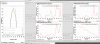
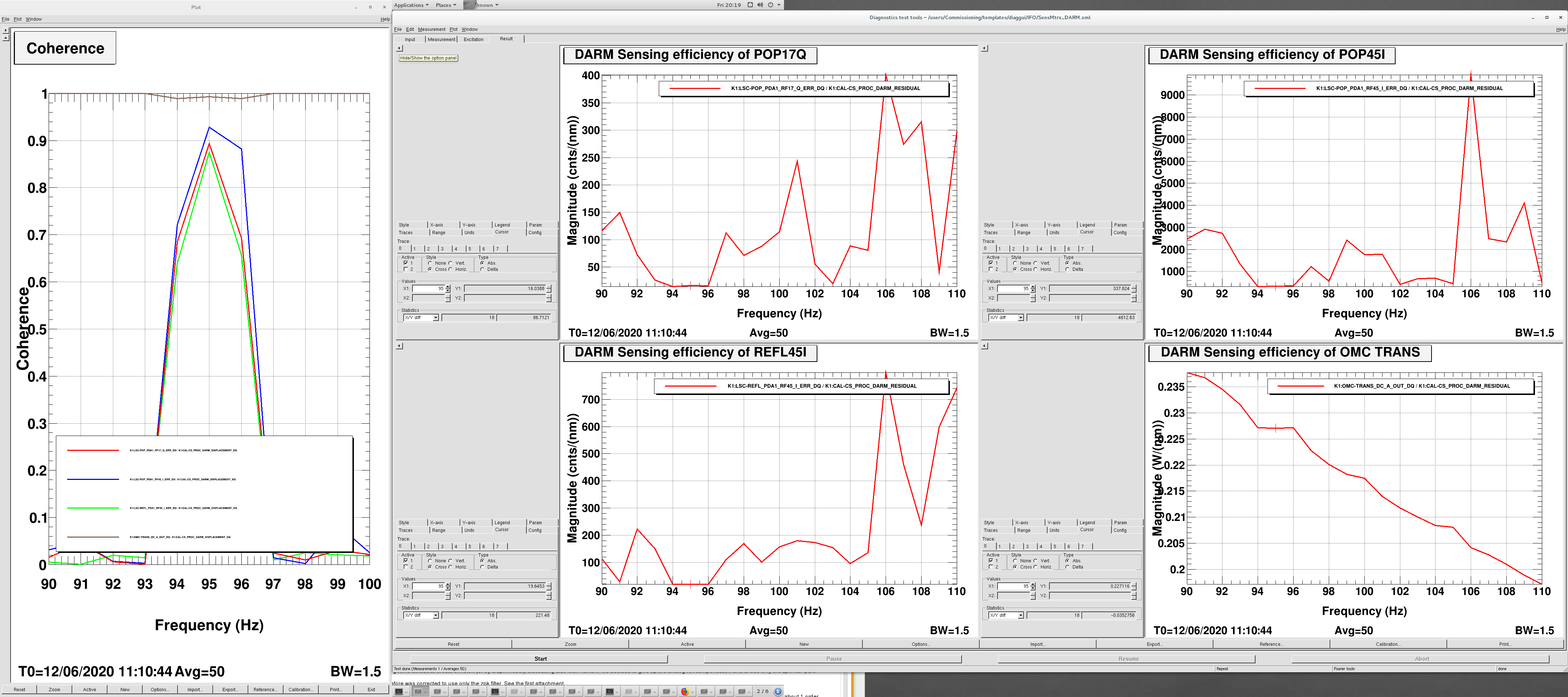
  4. Attached file shows the measurement result for DARM.
Images attached to this report
Comments to this report:
keiko.kokeyama - 23:51 Friday 12 June 2020 (14519) Print this report

To throughly compare with a simulation model, also phases (from an exc to signal) or signal signs have to be measured at just the exciation frequency.

keiko.kokeyama - 11:32 Monday 15 June 2020 (14532) Print this report

Here is the matxi with phases shown in ().

  MICH PRCL CARM DARM
POP17Q 41 (-180) 3.4 (180)   16 (-73)
POP45I 4100 (10) 3400 (1.8)   340 (120)
REFL45I 6.9 (6.0) 7.2 (0)   20 (-72)
OMCDC 7.3e-4 (0.77) 1.0e-4 (-100)   0.23 (110)
keiko.kokeyama - 20:29 Monday 15 June 2020 (14539) Print this report

The signal chain for the RF PD calibration is shown in the attached picture. The conversion factors are:
For 17 MHz signals = 0.8 [A/W] * 300 [V/A] * 10.9 (demod board) * 1638 [cts/V] = 0.23e-6 [W/cts]
For 45 MHz signals = 0.8 [A/W] * 450 [V/A] * 10.9 (demod board) * 1638 [cts/V] = 0.16e-6 [W/cts]

(Can anyone check the attached figure for the chain?)

The calibrated sensing matrix in W/m is:

[W/m] MICH PRCL CARM DARM
POP17Q 9.4e+3 (-180) 7.8e+2 (180)   3.7e+3 (-73)
POP45I 6.6e+5 (10) 5.4e+5 (1.8)   5.4e+4 (120)
REFL45I 1.1e+3 (6.0) 1.2e+3 (0)   3.2e+3 (-72)
OMCDC 7.3e-4 (0.77) 1.0e-4 (-100)   0.23 (110)

(orders of the numbers are very reasonable as sensmat numbers :)

The power fraction at each port is still not taken into account. At the next chance to enter the mine, I will try to measure them.

Non-image files attached to this comment
yuta.michimura - 22:21 Monday 15 June 2020 (14543) Print this report

The RF signal chain looks reasonable to me. Thank you!

keiko.kokeyama - 10:39 Tuesday 16 June 2020 (14546) Print this report

Thank you very much for checking!

keiko.kokeyama - 18:48 Friday 19 June 2020 (14578) Print this report

Here is the preliminary simulation result for the PRFPMI sensing matrix. 

Search Help
×

Warning

×