Ushiba, K. Tanaka, Akutsu
Afther the green work 10302, we also measured beam profiles of the transmitting IR beam at TMSY (Yend) for re-locating the IR QPDs in the IR Gouy phase telescope (GPT). In short, the measurement was not so good and should be done again....
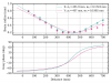
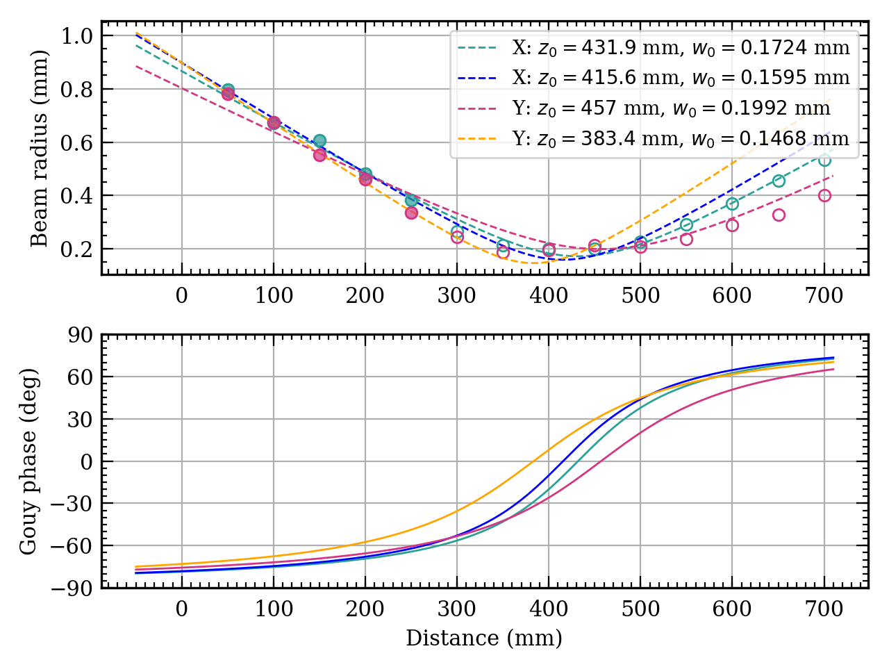
- Fig. 1 shows the measured data points and fitting curves using all the measured data.
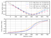
- Fig. 2 includes what Fig 1 shows, and additional fitting curves created by just using the first 1~4 points to fit. For horizontal (x), it seems ok, but for vertical (y), the difference beomes large after the waist position.
The procedure was (the naming convention of the optics follows the ver.7 of Nagano-kun's layout):
- We found RBS1 and RST3... were all mis-located or not fixed well. Probably we just left them as rough postions, though I don't remember well. Anyway we put RBS1 and RST3
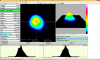
- Then we measured profiles of the transmitted IR beam after RST3. We found that the beam radii were wider than our expectation, and too collimated. For example, the beam profile at a distance of 3*25 = 75 mm away from RST3 is shown in Fig 3.
- Then we checked the upper optics like RLNS1 and RLNS2 and so on. We assumed that the IR beam from the EYT chamber should be well collimated, so the position of RLNS1 was not big effect. So we just left it as was. Anyway, we found the distance between from RLNS2 to RLNS1 were different from what the Nagano layout ( about 50mm!!), so we just re-locarted RLNS1 so that the distance became the nominal.
- Then we tweaked the micrometers on the moving stage for RLNS1 (and probably RLNS2), along with monitoring the beam width after RST3 so that the width became smaller to the nominal values like ~ 200um radius (400 um in diameter)
- After the tuning of the micrometers, the distance between RLNS1 and RLNS2 became (12.75~12.8)*25 mm, while the nominal designed value is 12*25mm.
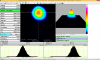
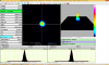
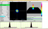
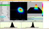
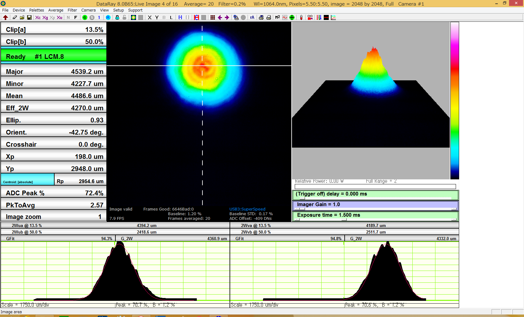
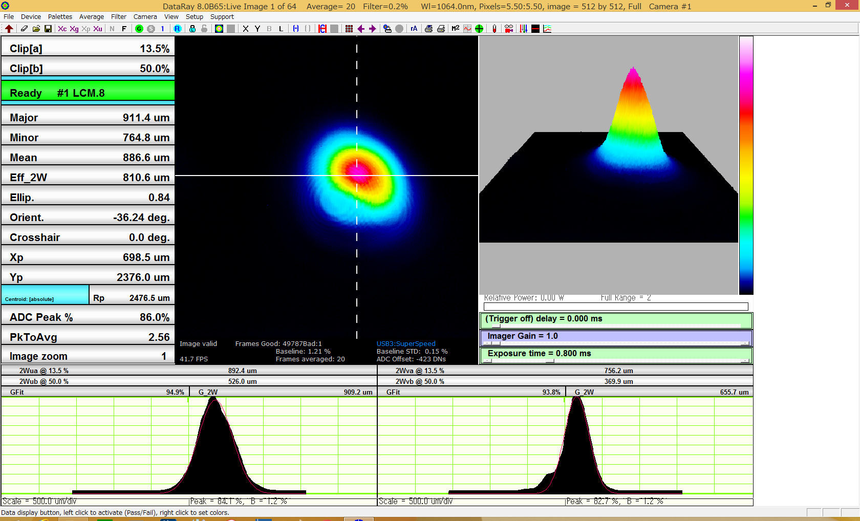
- Then we measured the beam profile after RST3 by assuming the origin point is RST3. The results are shown in Fig 1 and 2, as already discussed. By the way, some examples of the beam profiles are shown in Fig 4, 5, 6, and 7, where the distance are 50, 150, 400, and 650 mm, respectively. Note that the waist is around 400mm.
It seems the beam at the waist seems so roundy, but you can observe strange shapes at the far-away postions (as usual??). Moreover, as discussed already, the simple fitting is not good. Although the beam shape is so roundy at the waist, the radii evolution is extraordinary... it seems so flat. Probably it would be interesting if you fit those data with M^2- contained gaussian beam. Anyway, for the evoultion on the 'Y' (or vertical) axis, the choise of the data for fitting varies the results so much...
You know, the purpose of this meaurement to know Gouy phase evolution, and obviously it is inconsistent with two fittings for the Y axis (see Fig 2). Well, the relative phase difference seems somewhat preserved, so finally we can put the QPDs...
Addtinally, due to the lack of the space on the optical table, we put a BS (we could not find a "mirror" for IR at that time) to fold the optical path. As the IR beam would contain the other polatization, this BS might be problematic... but in that case, we cannot use the BS for dividing the beam to two QPDs, if such a thing actually be happening.
Maybe we did too focusing and the aberration would make this kind of strange shapes. We will tweak the distance btwn RLNS1 and RLNS2, and see what will happen later.