K. Tanaka, Akutsu
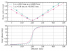
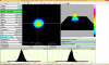
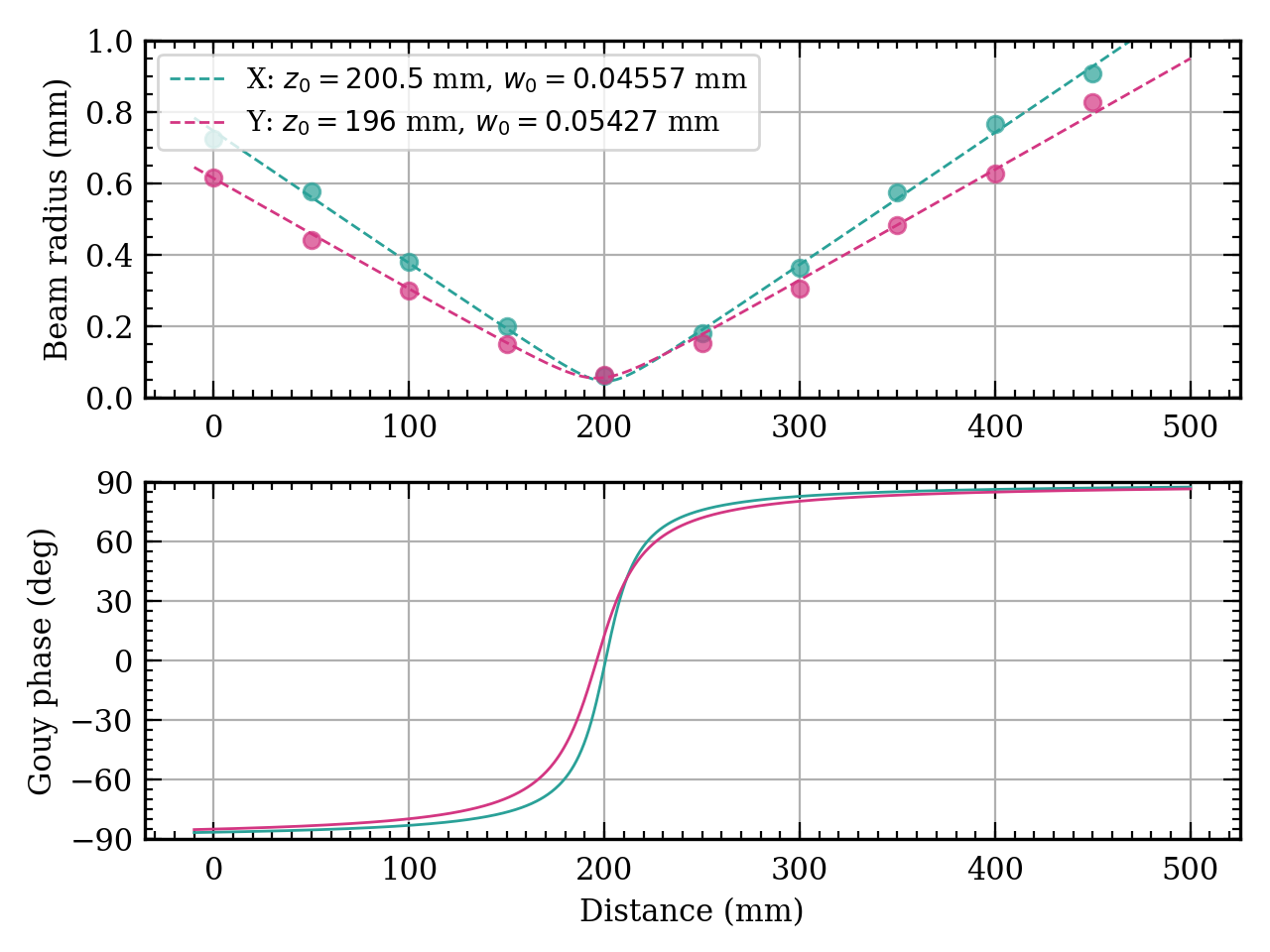
Measured profiles of a green beem in the gouy phase telescope (GPT) of the TMSY at Yend. We found that the waist radius was ~ only 50 um, while the design should be around 200 um. We did not adjust QPDs for the green GPT today.
- Fig. 1 is the result of the fitting to the measured data. The gouy phases for horizontal and vertical are also shown. It might not be impossible to put the QPDs by separating 90-120 deg but...
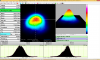
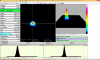
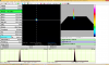
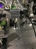
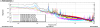
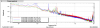
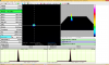
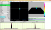
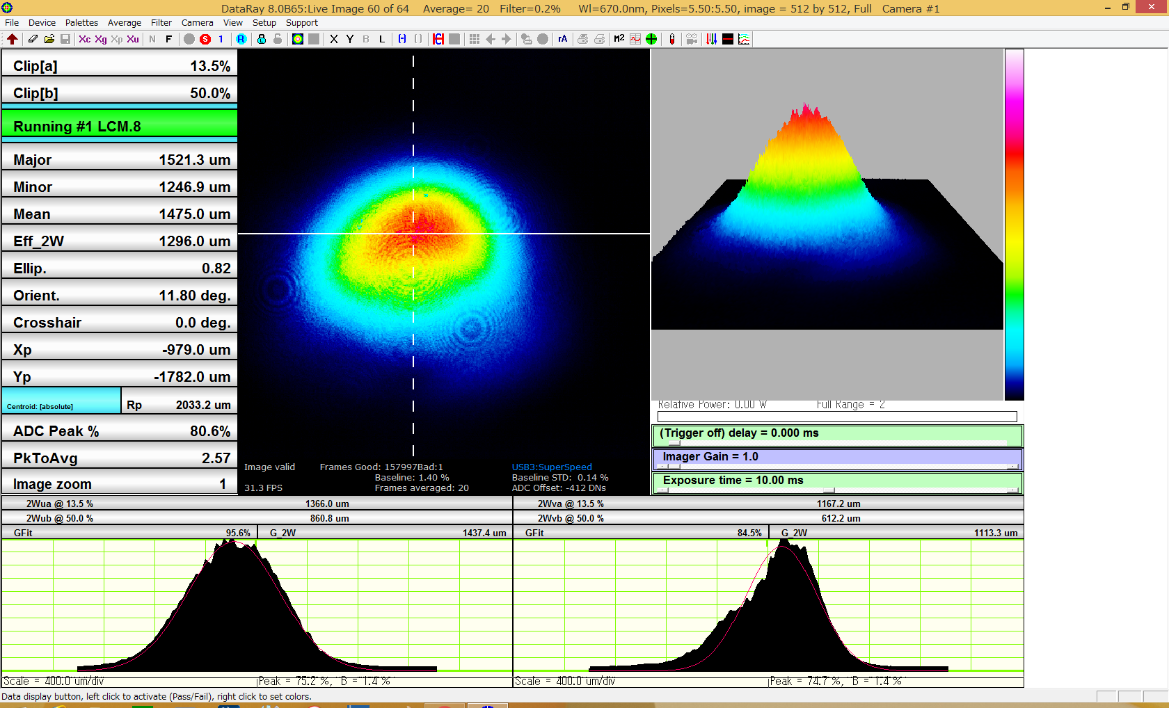
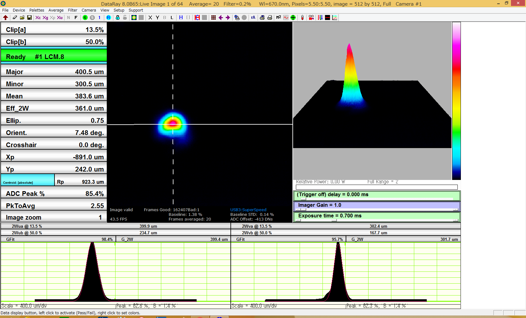
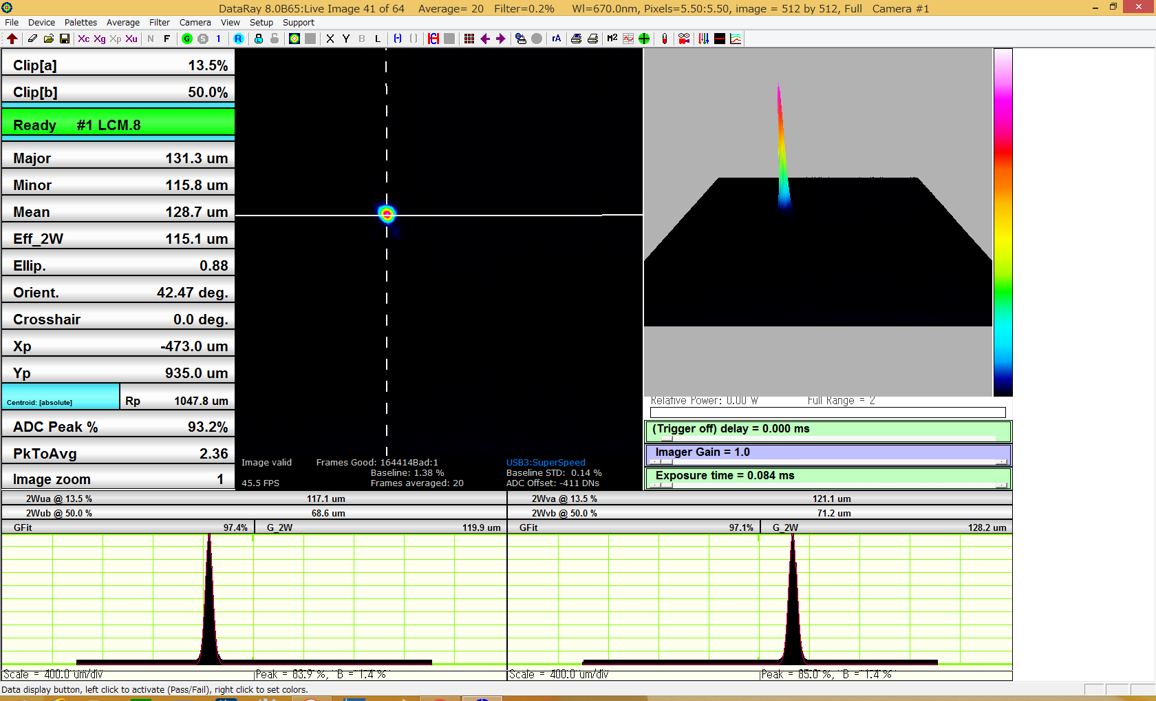
- Fig 2-5 are the display for the beam profiler WinCamD-LCM, which we used today. As shown in Fig. 6, we used the sensor head upside-down so that the USB cable won't intefere against the other optics.
- Fig 2 and 3 are of before the waist. Fig 4 is close to the waist. Fig 5 is of after the waist.
According to my rough estimation, to help this situation, for example the lens for this green GPT should be replaced from the current one (f=500mm) with a one with 1000 mm focal length as follows:
- Let q0 is the q-parameter just before the lens. Let q1 is just after the lens. So 1/q1 = 1/q0 -1/500.
- The distance from the lens to the 50um-waist is about (18+8)*25 = 650 mm, so q1 = -650 + i Zr, here the Rayleigh range Zr = pi*(50e-3)^2/532e-6 = 14.7 mm.
- So, q0 = 2150.8123 +161.7796*i, which means the waist radius of this beam is ~0.16 mm; this is relativelly collimated but out of the Raylegih range. So changing the location of the lens like 10-20 mm would not affect so much the real part of q0. Such changes would just change the position of the waist after the lens with almost preserving the waist size... So you need to consider changing the forcal lenth of the lens, such as 1100 mm to obrain nice waist size instead of 50 um.