[Matteo, Aritomi]
Summary
We realigned POP_P camera and measured the power on POP and POP_P cameras as function of HWP angle. We then took pictures of POP and POP_P in different locking situations
Details
The POP layout can be found here.
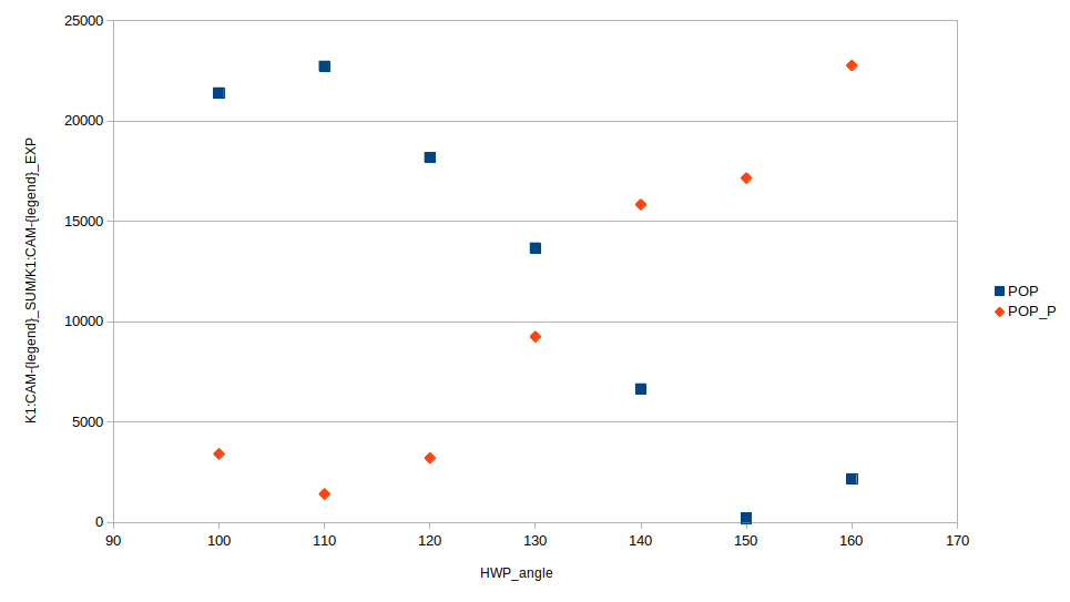
First we moved POP_P camera closer to TFP. The new distance between TFP and POP_P camera is 25mm. Note that other optics position in the current layout are not correct and will be reported later. POP camera is also at 25mm from TFP, so both images have the same scale. Then we measured POP and POP_P power as function of HWP_angle. POP power is computed as K1:CAM-POP_SUM/K1:CAM-POP_EXP while POP_P power is computed as K1:CAM-POP_P_SUM/K1:CAM-POP_P_EXP. Those channel are not stored. The result of this measurement is in Fig.1. With the exception of POP_P@150deg, the plot is as expected. We decided to fix HWP_angle = 110deg.
Then we checked the cameras in different configurations: MICH_locked, Xarm_unlocked (but aligned), Xarm_locked, Yarm_unlocked (but aligned), Yarm_locked. In all those configurations, the optimal HWP_angle was found to be around 110deg (for X/Yarm_locked the beam fluctuation was quite large and was difficult to find the optimal point precisely).
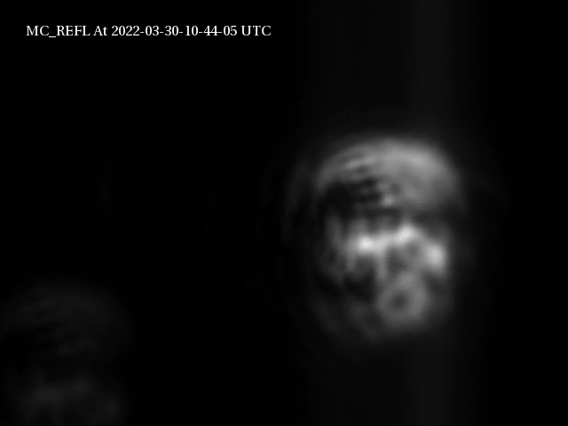
Finally we took pictures of POP and POP_P cameras in the mentioned configurations, as well as the power on each camera (note that between POP and POP_P camera images there is a left/right inversion).
| condition | K1:CAM-POP_EXP | K1:CAM-POP_SUM | K1:CAM-POP_P_EXP | K1:CAM-POP_P_SUM | POP_SUM/POP_EXP | POP_P_SUM/POP_P_EXP | Note |
| MICH_locked | 154 | 3.50E+06 | 2125 | 3.00E+06 | 22727.3 | 1411.8 | Fig.2 |
| X_unlocked | 800 | 5.40E+06 | 2443 | 2.10E+06 | 6750.0 | 859.6 | Fig.3 |
| X_locked | 800 | 4.10E+06 | 8446 | 1.50E+06 | 5125.0 | 177.6 | |
| Y_unlocked | 800 | 5.80E+06 | 4949 | 2.40E+06 | 7250.0 | 484.9 | Fig.4 |
| Y_locked | 536 | 3.90E+06 | 19048 | 2.40E+06 | 7276.1 | 126.0 | Fig.5 |
| | | | | | | | |
| X_unlocked | 750 | 5.10E+06 | 2933 | 2.60E+06 | 6800.0 | 886.5 | |
| X_locked | 750 | 3.70E+06 | 13665 | 4.00E+06 | 4933.3 | 292.7 | Fig.6 |
For X arm some clipping seems to happen which makes POP image very strange. In both X and Y arm the power on POP_P decreases when the arm is locked and in Yarm POP image the beam shape seems to improve when arm is locked.


_OUT_DQ.png)


_OUT_DQ.png)