K. Miyo, Y. Fujii,
log on 2019 August 13th,
= For all the suspensions =
- we added damping filters for BF to BF damping in L and T, for all the type-A suspensions.
- After a test (lkog#9941), we implemented the sensor correction filters for IP-stage for all the type-A suspensions.
= What we did =
-
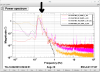
In order to supress the amplitude at about 150mHz, BF to BF damping filters were implemented:
- This was done for L and T.
- This filter focues on only ~150 mHz mode.
- Since the BF sensor, so-called BF-LVDT, reads the relative motion between the gruond and the BF-body, this filter should introduce the seismic motion to the suspension. For further suppression, we will try sensor corretion at BF stage. Now, for the damping purpose, this was installed.
-
We implemented the sensor correction filters for IP-stage for all the type-A suspensions:
- This filter subtracts the seismic signal from IP-LVDT signal. The sismic motion was measured by seismometers on the ground. This filter was implemented to IP-L and IP-T dof.
-
we added seismometer signal (in displacement) to the IP-LVDT sensor signal, with -1 and
-
(1st trial) with 3 mHz cut-off for ETMX and ETMY, 10 mHz cut-off for ITMs.
- Since when this work was done, it looked that the lower frequency amplitude of the seismometer spentrum was not dominant compared to the micro-seismic peak for ETMs. For ITMs, to shut out the lower frequency component of the seismometer spentrum, we set 10mHz cut-off for a trial.
-
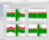
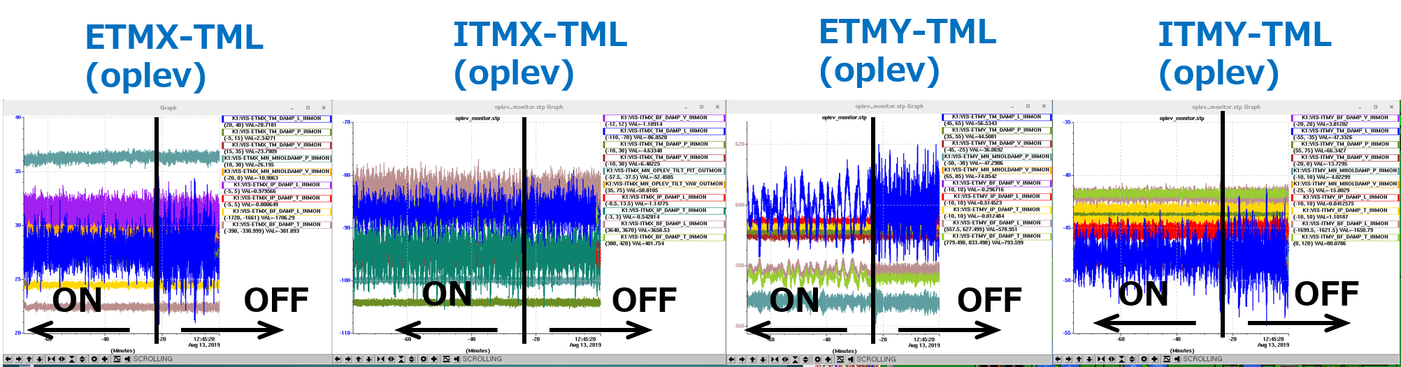
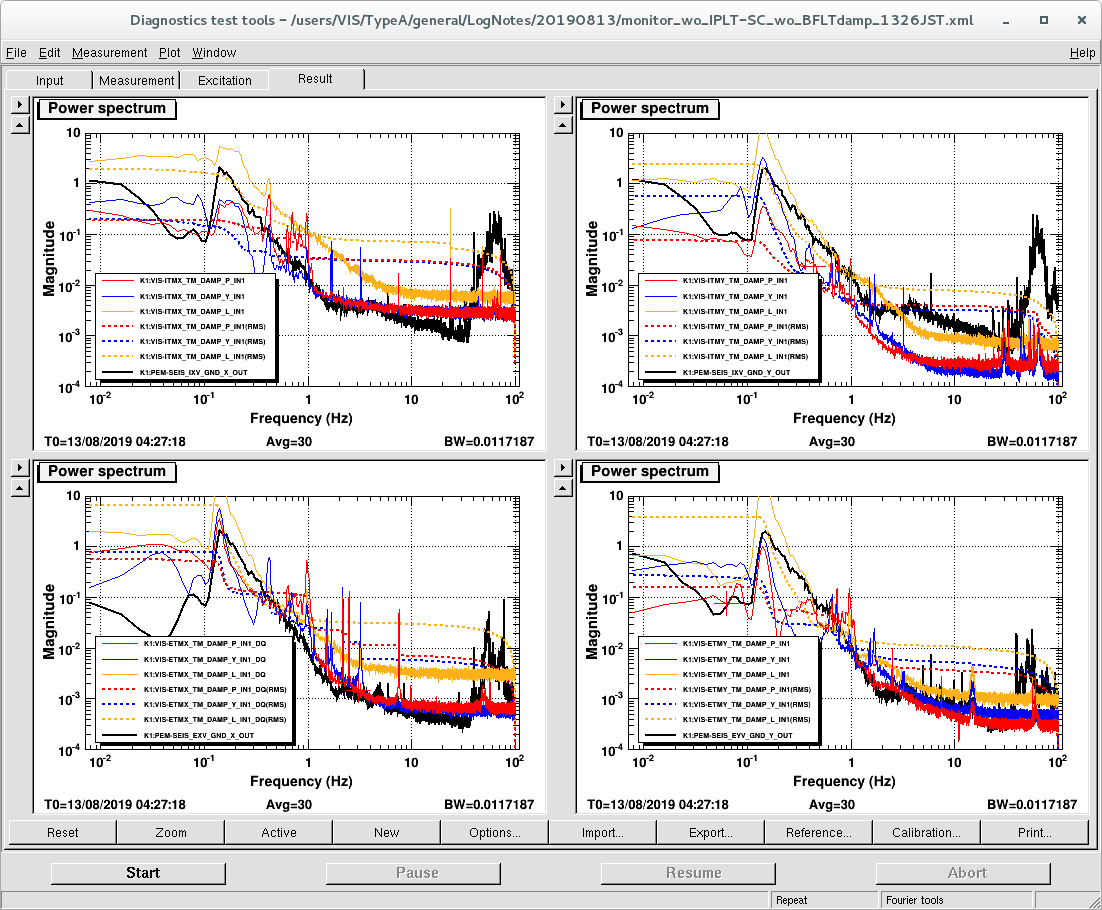
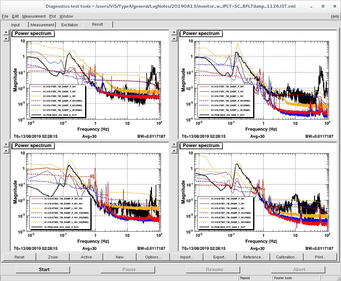
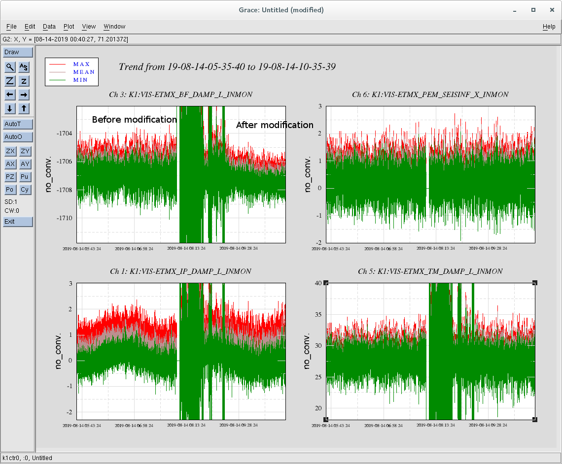
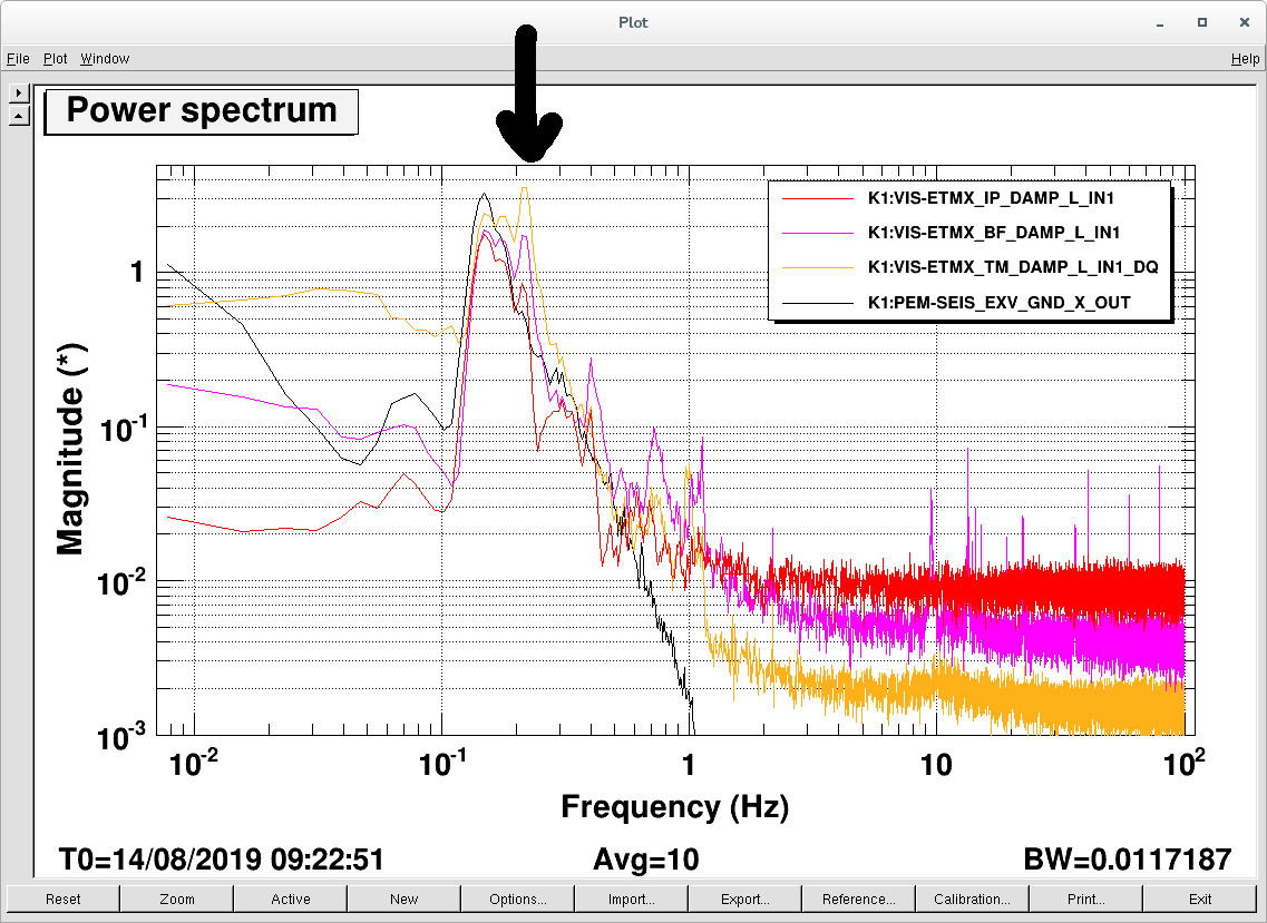
The spectrum and the time-series/spectra with and without the sensor correction is shown in Figure 1 to 3 (BF-damping filter is also closed).
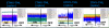
- Figure 1: the timeseries, blue curves show the TM-L oplev signals
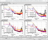
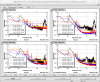
- Figure 2 and 3: the TM oplev spectra w/ and w/o (sencor correction + BFdamping). orange: TM-L, red: TM-P, blue: TM-Y and black: ground in vel [*].
- It was found that the sensor correction worked, however, it led larger amplitude at lower frequency region like 10mHz, especially for ETMY.
-
(2nd trial) with 30mHz cut-off for all the type-A suspensions
- During the seismometer characterization work, it was known that the seismometer signal at lower than ~10mHz depends on tilt-motion or so. and the amplitude at that region is changed day by day.
- In order to take into account of this issue, we set 30mHz cut off at the 2nd trial.
- The result is to be posted soon, however, it looked the 30mHz cut-off fiter also worked. The difference will be compared.
-
(1st trial) with 3 mHz cut-off for ETMX and ETMY, 10 mHz cut-off for ITMs.
- At least, for the damping purpose in the currennt situation, it looked that using both the sensor crrection and BF-L/T damping gave better spectum.
- Now the 30mHz cut-off filter is implemented to the all the type-As.
- Currently this sensor correction is switched on when the TWR_DAMPED is requested (should be).
- If the suspension is quiet enough in an inertial coordinate, the length-oplev should see the ground motion. Still it seems that the amplitude of TML is higher than the amplitude of ground at 150 mHz, we can suppress the peak more, somehow? (the TML is in the attached plot not calibrated though. except for ETMX, the spectra shows mostly displacement, for ETMX, the actual displacement is smaller than the attachement by a factor of 2, this is to be posted as another log).
- To be continued.
[*] I found that In Figure 2, the BF-L damping filter in ITMX was ON though.