Reports 1-1 of 1 Clear search Modify search
VIS (General)
fabian.arellano - 10:53 Wednesday 17 July 2019 (9541) Print this report
High power coil driver modification

With Terrence, Enomoto-kun and Shimode-san

This entry points out to the relevant components in a high power coil driver which need to be modified in order to increase the output current.

Two strategies are reported here.

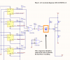
The relevant circuit diagram can be found here: D1503503.

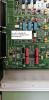
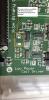
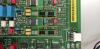
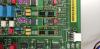
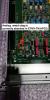
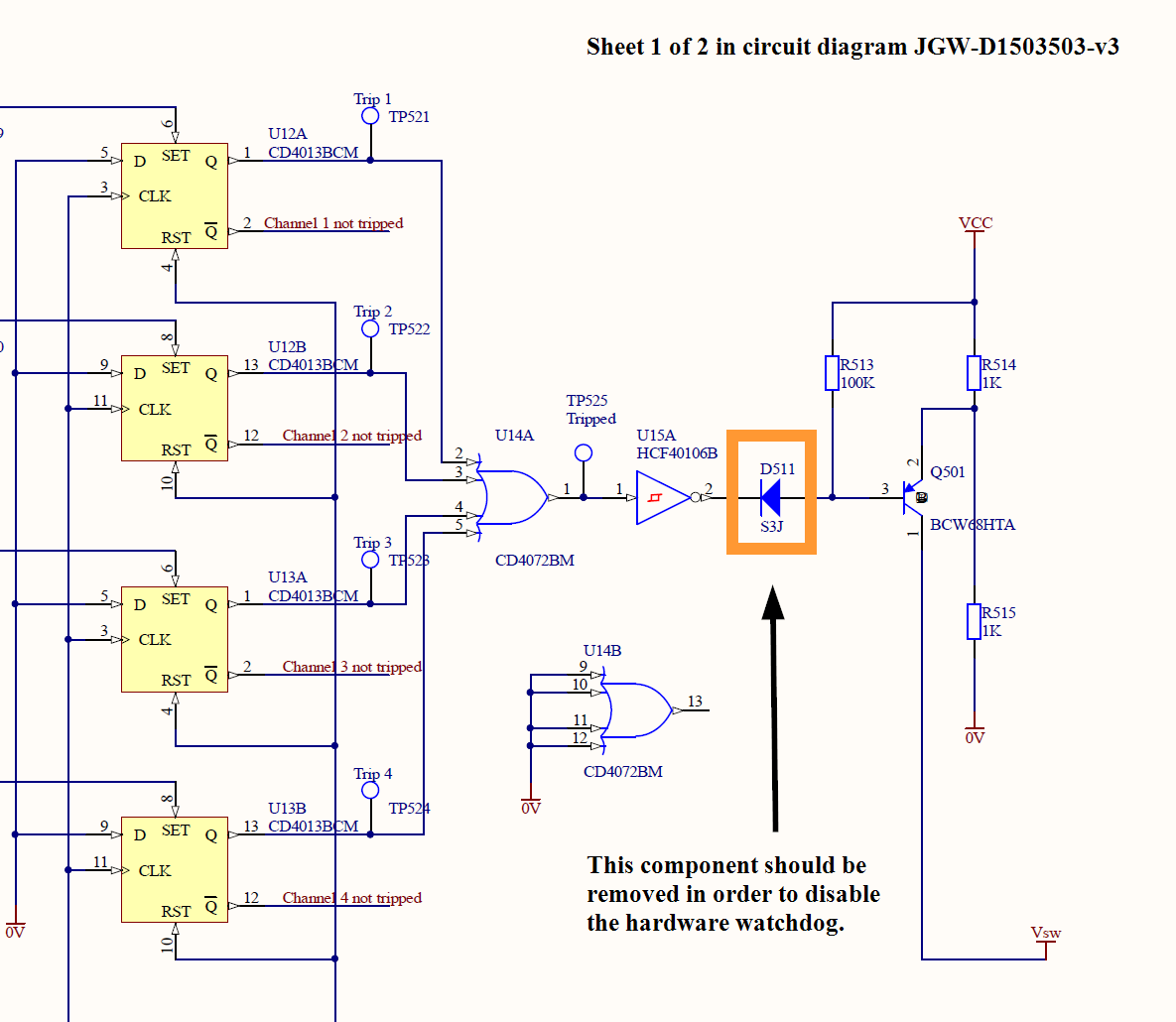
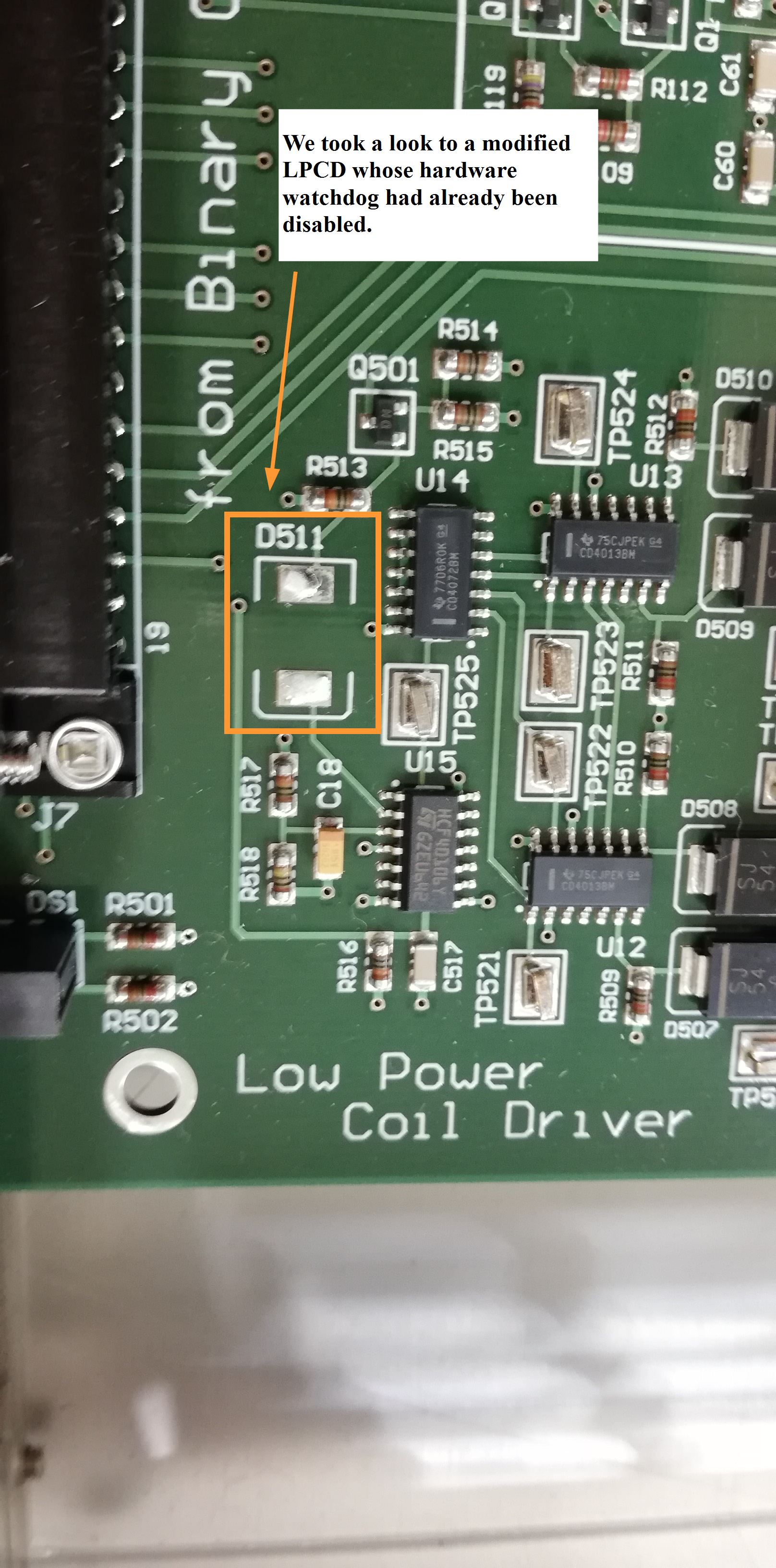
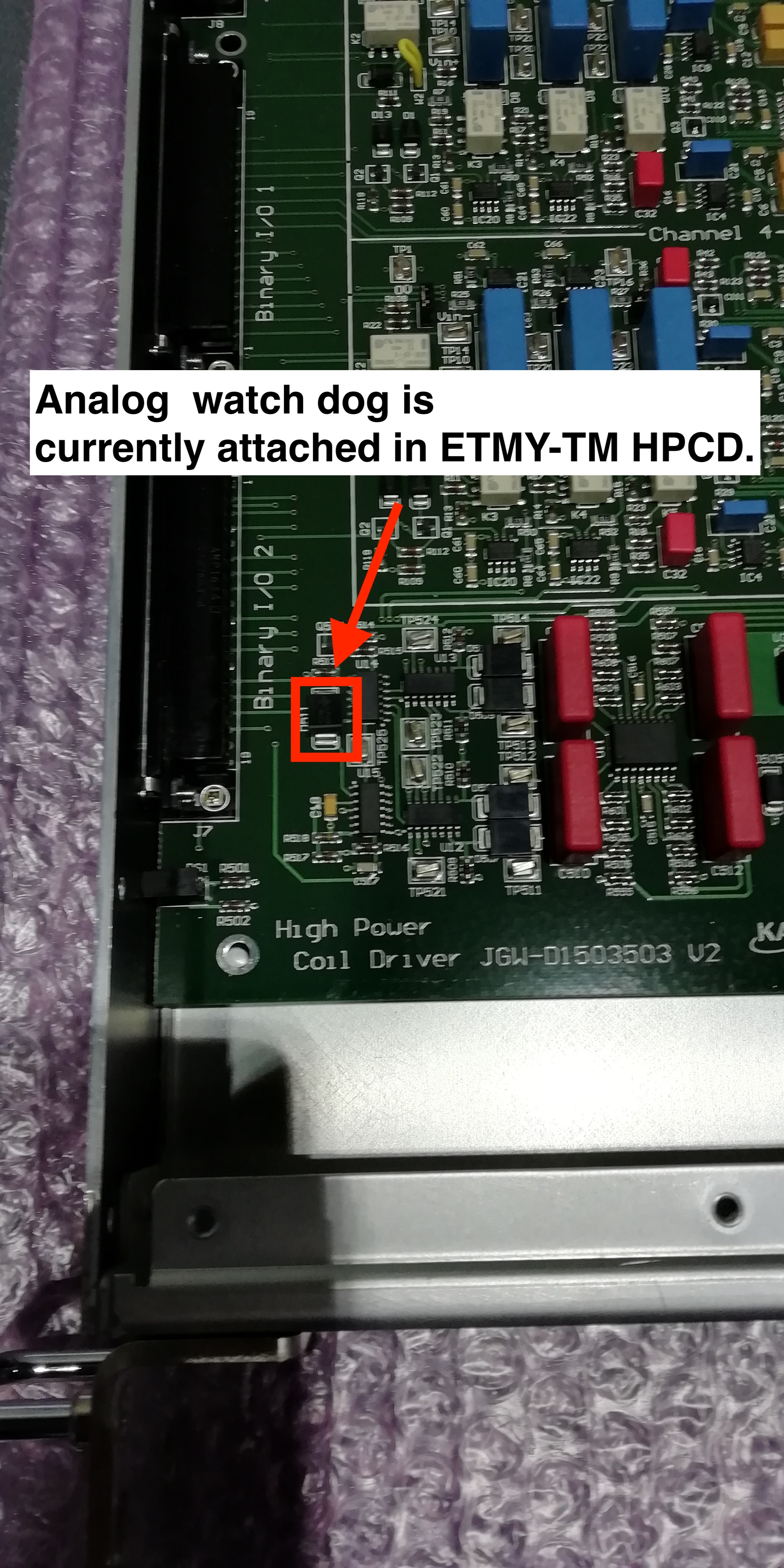
How to disable the hardware watchdog

This has done before by Shimode-san by removing D511 diode. See te first three pictures.

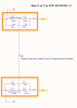
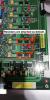
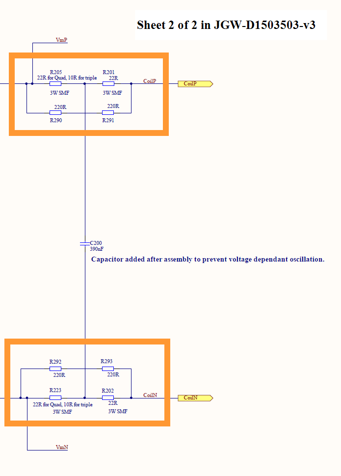
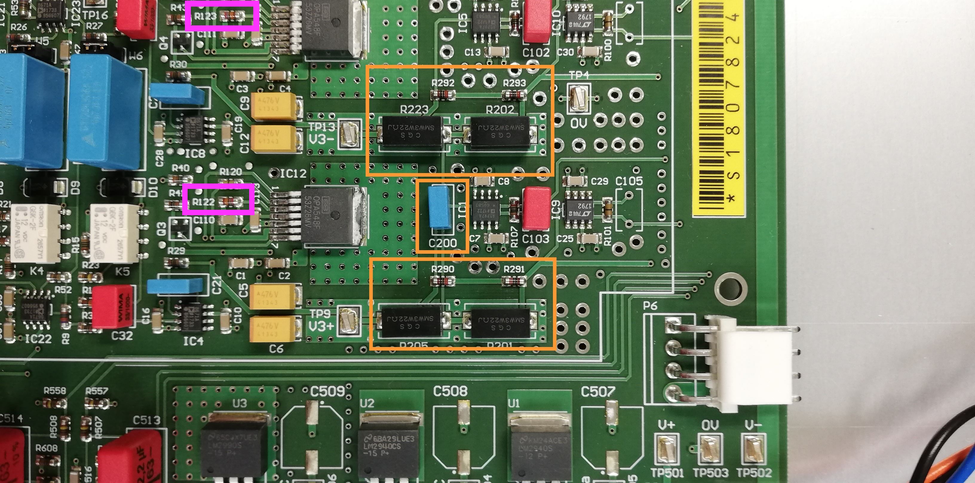
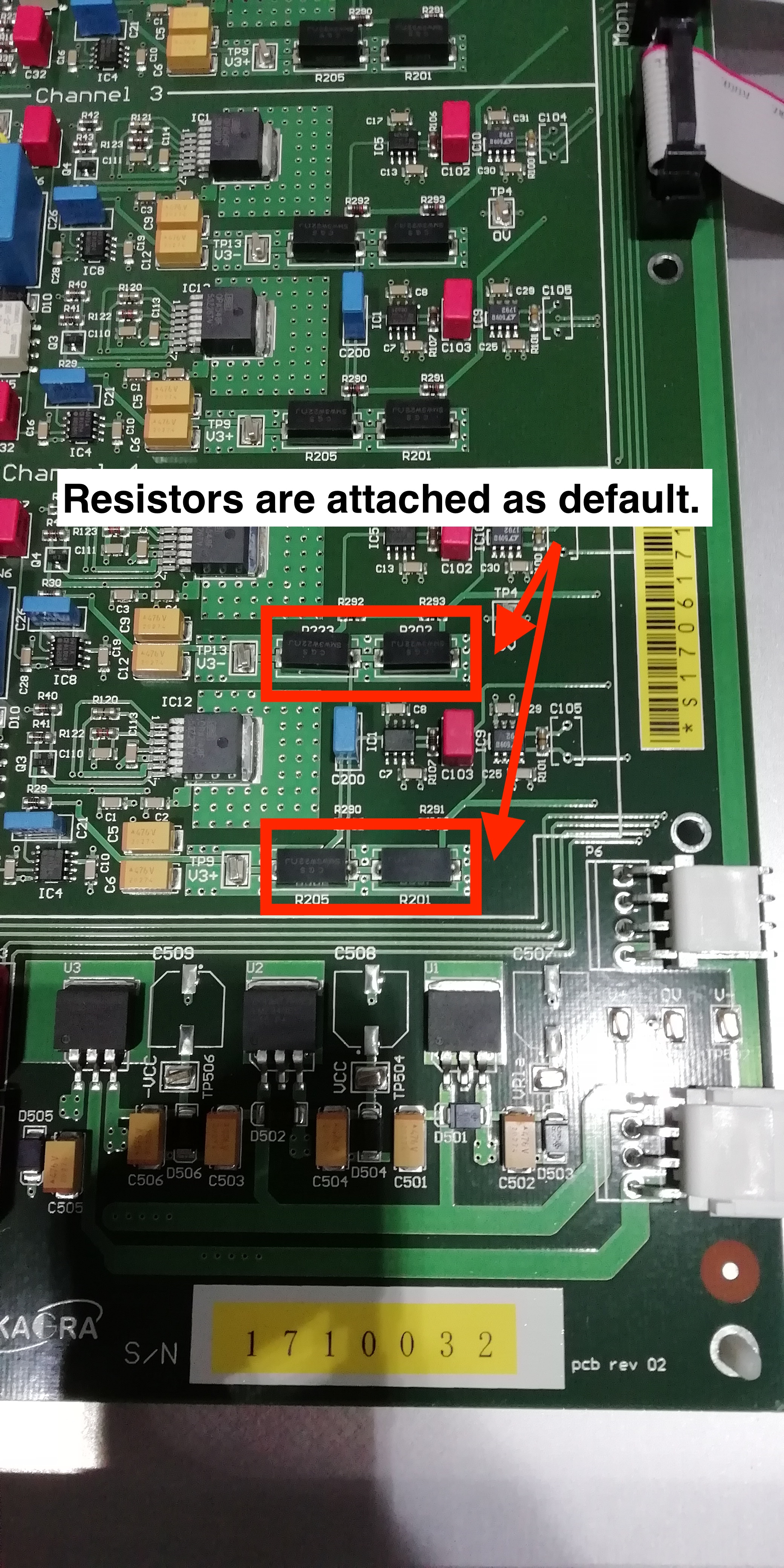
Resistors at the output which could be removed in order to decrease the impedance of the closed circuit

In the circuit diagram, at the CoilP terminal, the resisistors are called R201, R205, R290 and R291. At the CoilN terminal they are R202, R223, R292 and R293. See the fourth and fifth pictures. Note that in between the two terminals there's a capacitor whose effect should be considered when removing the resisitors. According to the diagam its aim is to prevent voltage dependant oscillations.

The third strategy is to increase the gain at any of the amplification stages.

Maximum current limit of the OPA548

Raising the maximum current limit of the OPA548 might also be useful in the future (now set to 0.25 A). This is achived by changing the value of the R122 and R123 resistors. We should checked what we have now. See the sixth picture.

Images attached to this report
Comments to this report:
tomohiro.yamada - 16:34 Wednesday 17 July 2019 (9546) Print this report
[RTakahashi, Yamada]
 
We went to Yend to check a high power coil driver, which is currently used for ETMY-TM actuators.
Analog watch dog is attached and output resistors are also attached.  So current configuration is as "default".
We have possibility to achieve more stable mass-locking by modifying a circuit.
See attached pictures for details.

Also, we measured electrical resistance of cables at feed-through in EYV.
Results are following.
Pin1-6(H1 actuator): 72.2 Ohm
Pin2-7(H2 actuator): 72.5 Ohm
Pin3-8(H3 actuator): 72.6 Ohm
Pin4-9(H4 actuator): 72.5 Ohm
Images attached to this comment
mark.barton - 17:42 Wednesday 17 July 2019 (9548) Print this report

For the record, note that removing D511 means that the output current never actually shuts off, but the chassis still reports that there has been a trip when a fairly low threshold has been exceeded on one or more channels. So the trip signals cannot be used as either an indication that the output is off, or an indication that any overload condition was serious.

Therefore, in the short term, Guardian and similar software should be programmed to completely ignore the trip signals from modified HPCDs, and in the long term, the threshold should be adjusted to something useful.

fabian.arellano - 11:33 Thursday 18 July 2019 (9563) Print this report

An addition to Mark's observation is his entry on how the Type B Guardian was modified. Please see enrtry 8586.

fabian.arellano - 14:11 Thursday 18 July 2019 (9567) Print this report

Yamada-kun enquired about the status of the HPCD modification to Shimode-san:

  • Before modification the maximum current was 40 mA limited by the hardware watchdog.
  • Before any modification to the current source itself he disabled the watchdog and measured to output to be 64 mA.
  • With the watchdog disabled he modified the gain in the current source and achived 130 mA output.
  • He decided that disabling the watchdog entirely was not a good idea. He raised the limit to 120 mA instead.

The modification increases the current limit from 40 mA to 120 mA, limited by the hardware watchdog.

tomohiro.yamada - 22:30 Thursday 18 July 2019 (9574) Print this report
[R.Takahashi, T. Yamada]
With AEL group and VIS group.
 
We replaced ETMY-TM HPCD from default one to high-power-HPCD.
Since new one generate larger heat than default one, we made blank space above and below HPCD (See an attached picture).
Also, we keep a transparent plastic sheet open not to prevent air flow.
Images attached to this comment
Search Help
×

Warning

×