[K. Nagano, Akutsu, K. Tanaka, Kita, Aritomi with help from Tanioka and Y. Fujii]
In daytime last week, we worked for dampling control of TMS-VISX.
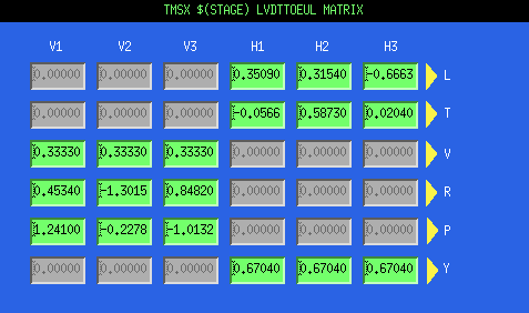
After trial and error, we could engage 6 DoF damping control somewhat using LVDTs .
.
# What we did
Before our work in Kamioka, test of damping control with LVDTs was tested in Mitaka (for datail please see here).
Thus, at first, we copied Mitaka's setup (diagonizing matrix, filter shape and gain value) and tiried to engage damping control with the same setup as Mitaka.
(Note polarity of LVDT and geophone was confirmed after installation in klog6389 and klog6414)
Although we could close all loop for horizontal DoFs (yaw, transverse, and logitudinal) simultaneously, vertical loop could not closed.
After we close the vertical loop, the TMS-VIS's motion got larger.
This seems because the gain was too large and we decided to modify the values of gain.
To do that, we close damping controls of six DoFs one by one and measured open loop gains.
In this step, we tuned gain values also.
The measured result was saved in /kagra/Dropbox/Personal/Nagano/20181005/.
As a result, we found control gain of roll and vertical loop were too large and reduced them by a factor of 0.6 (roll) and 0.5 (vertical).
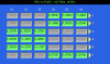
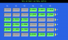
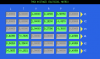
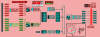
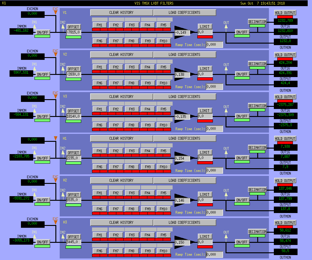
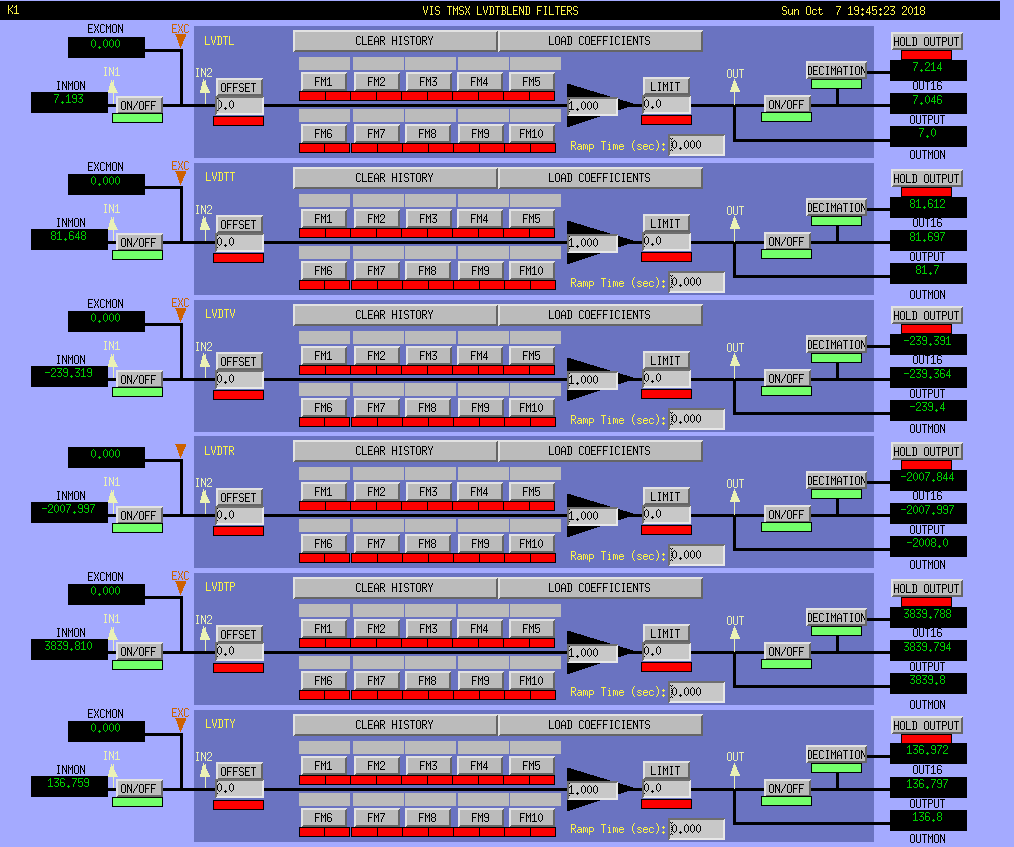
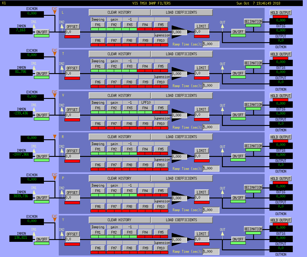
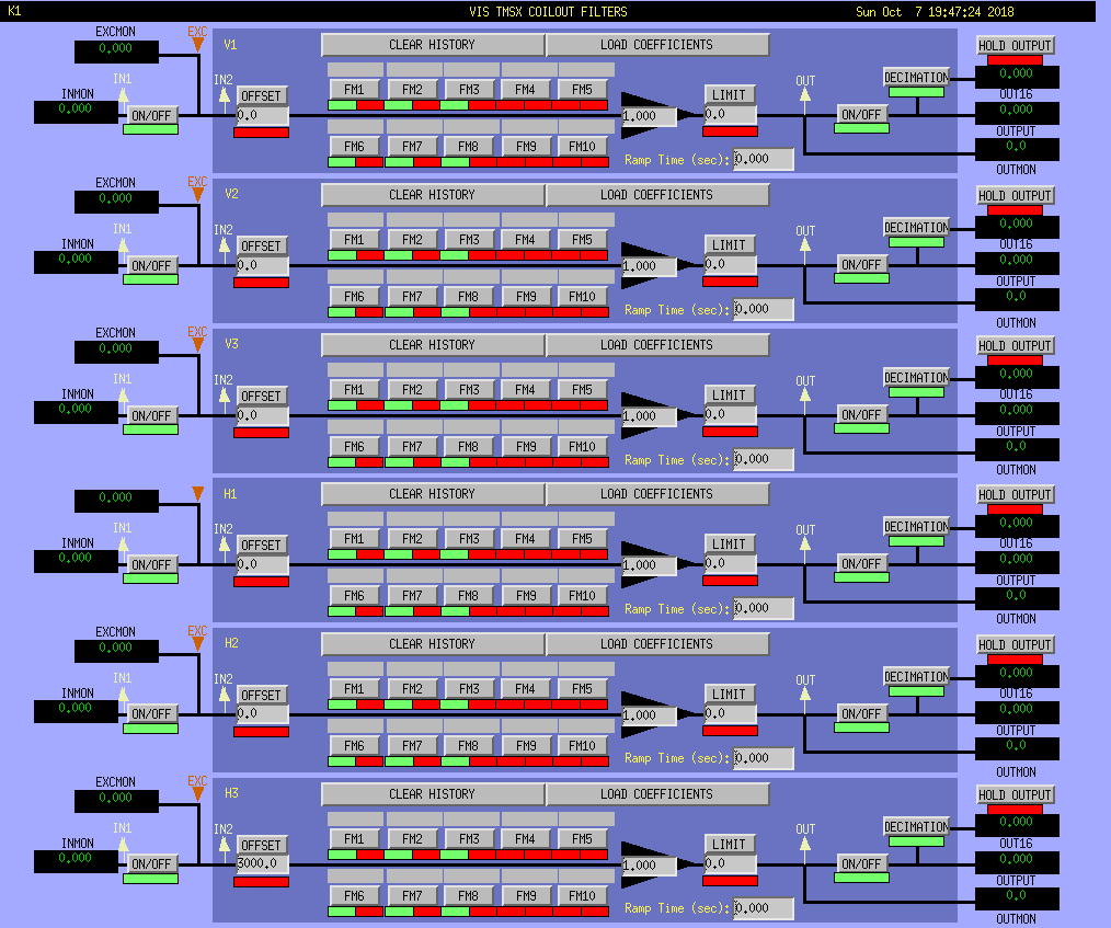
In the end, we could engage 6 DoF damping control somewhat with the setup shown in the attached figures (2nd-9th, 10th shows overview).
(If you wanted to close loop, please put ONE in gain setting in DAMP filters.
Mayby it's better to close horizontal DoF loops at first.)
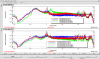
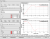
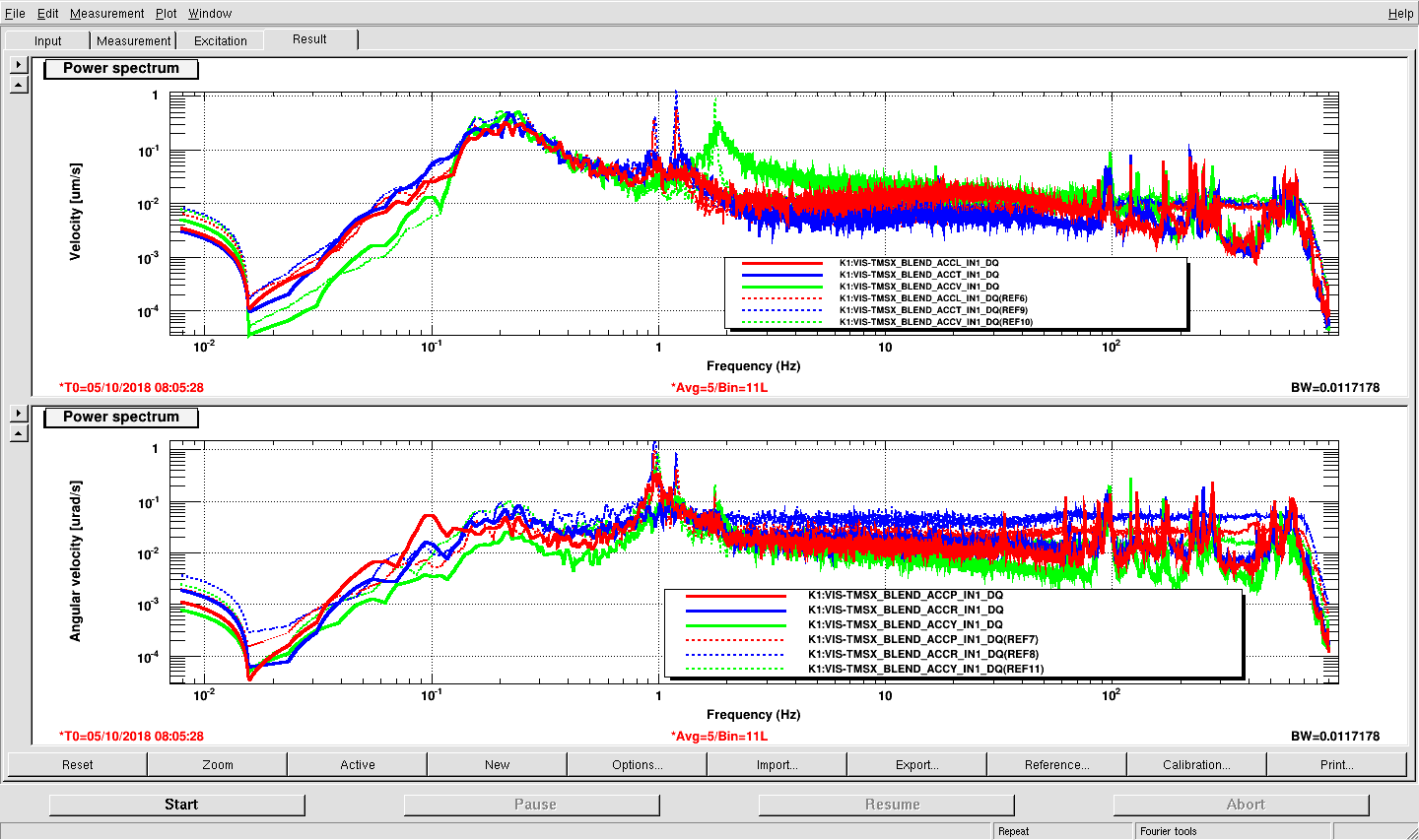
The damping result is shown in the attached 1st figure.
(Dashed lines, without damping; solid lines, with damping.)
They show the velocity spectra measured with geophones.
The mechanical resonance peaks were reduced by a factor of about 0.1-0.5.
# Remaingin problems
## Coupling from roll to vertical
In this work, we found there are lage coupling from roll to vertical maybe in actuation part.
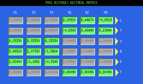
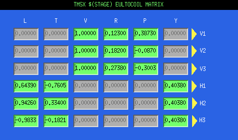
Actually, we did NOT tuned output matrix (EUL2COIL MATRIX).
If we tuned it, we may be able to increase gain in roll loop.
## LVDT noise is large
Currently, we use only LVDT in damping control although the TMS-VIS has geophones.
Actually, LVDT noise is large and it is induced by our controll loop.
As a result, the noise floor of TMS-VIS motion get large when we engage damping controls.
This situation can be improved if we use geophones too in dampling control.
However, since geophones are not effective below sub-Hz, we should implement hierarichical control, that is, we use LVDT in low frequency (<0.5 Hz ??) and geophoen in high frequency (0.5 Hz< ??).
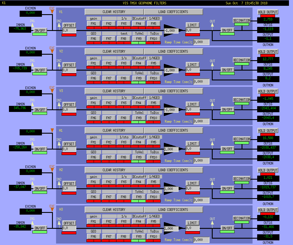
## Strange behavior of geophone filters
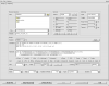
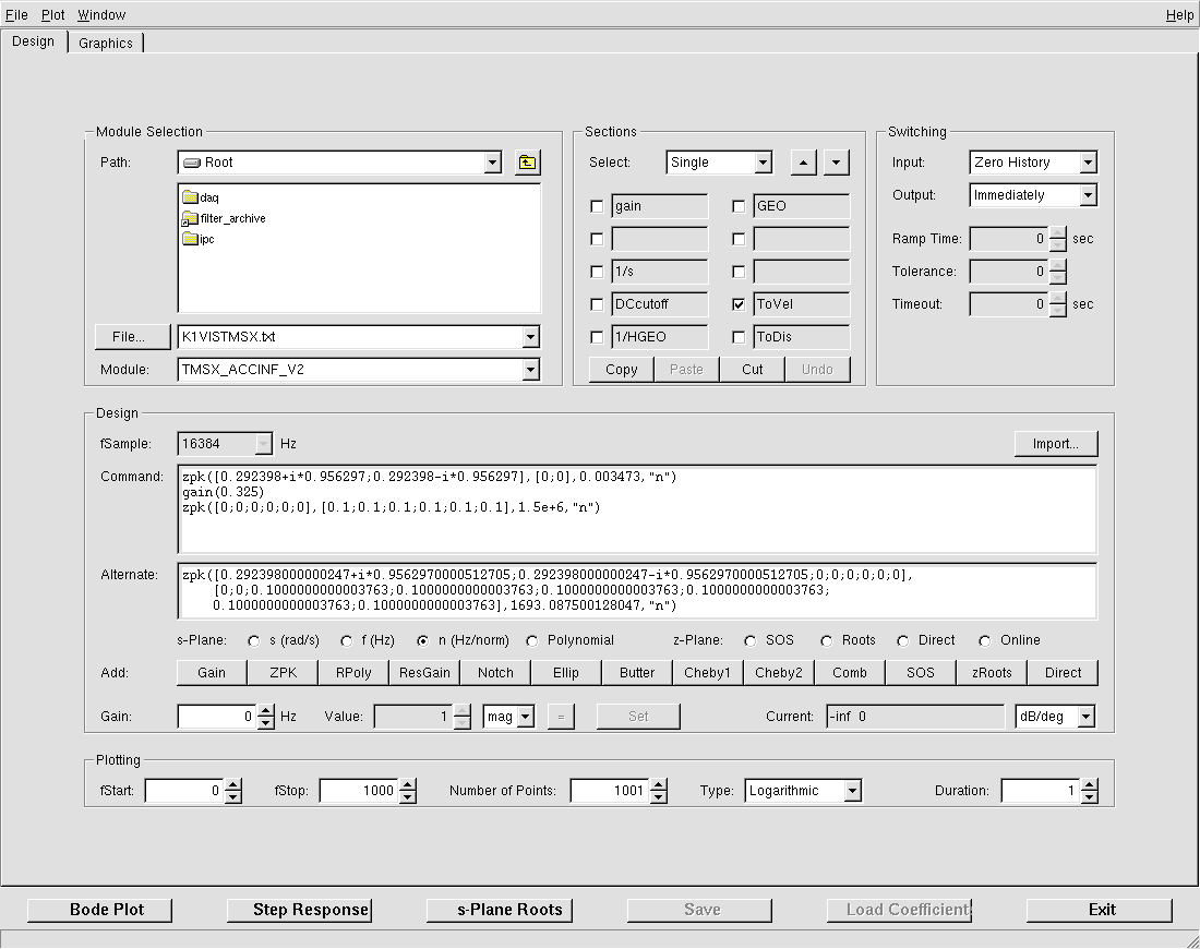
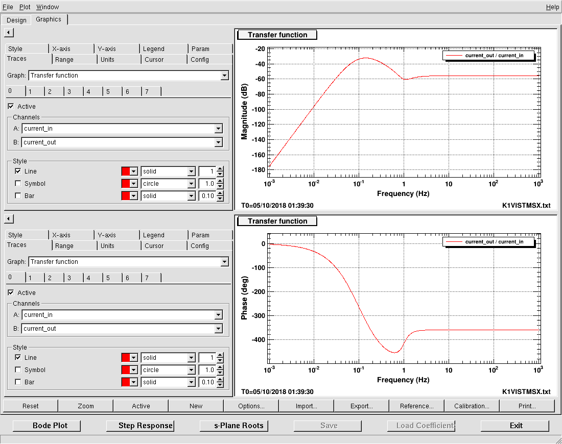
As shown in the 5th attached figure, we put calibration filters from counts to velocity in geophones
The filter shape is shown in the 11th and 12th attached figure.
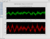
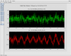
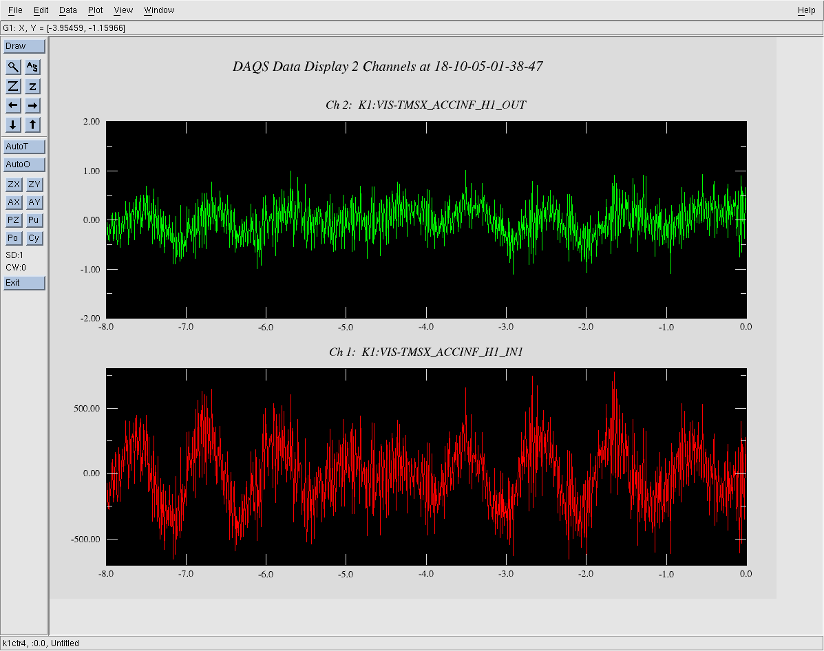
With this setup, we saw a strage behavior as shown in the 13th and 14th figure.
Just after turn on the filter (or clear history), the time series data was like the 13th figure and it seems OK.
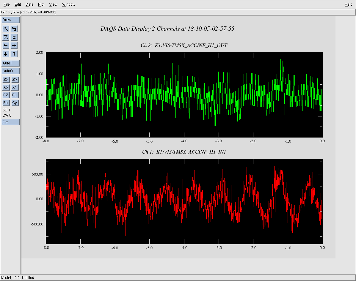
However, after a while (~ 1 hour or so), we saw some strange (discretized?) signal shown in the 14th figure.
Does anyone know how to solve this problem?


