| Port Number | #1 | #2 | #3 | #4 | #5 | #6 | #7 | #8 |
| Channel | LVDT V | LVDT H | Geophone V | Geophone H | IR QPD1 | IR QPD2 | GR QPD1 | GR QPD2 |
ADC0
| Port Number | #5 | #6 | #7 | #8 |
| Channel | Misc 1 | Misc 2 | OpLev QPD | IR/GR PD |
DAC0
| Port Number | #4 |
| Channel | LVDT H |
Not assigned yet: LVDT V (DAC)
Note1: V and H means vertical and horizontal, respectively.
Note2: Misc 1 and 2 in ADC0 are just spares and are not connected to anything in RT model for now.
Note3: Since we did not have usable port in DAC in this moment, we could not assigne actuation channel for LVDT V .
.
During this work, we found that there were no fasten metal (TOME KANAGU) in DAC0 port #4.
We should install it.
# Signal checking
At first, we could not see any signal in LVDT H3 due to the same reason as reported in klog5462.
We struggled to solve this problem and found that LVDT H3 signal could be seen in the same cable connection during test in NAOJ.
(In fact, we would to avoid the same setup since in the setup cable should be crossed. However, we could not found good solution. Thus, we just copied NAOJ's test setup.)
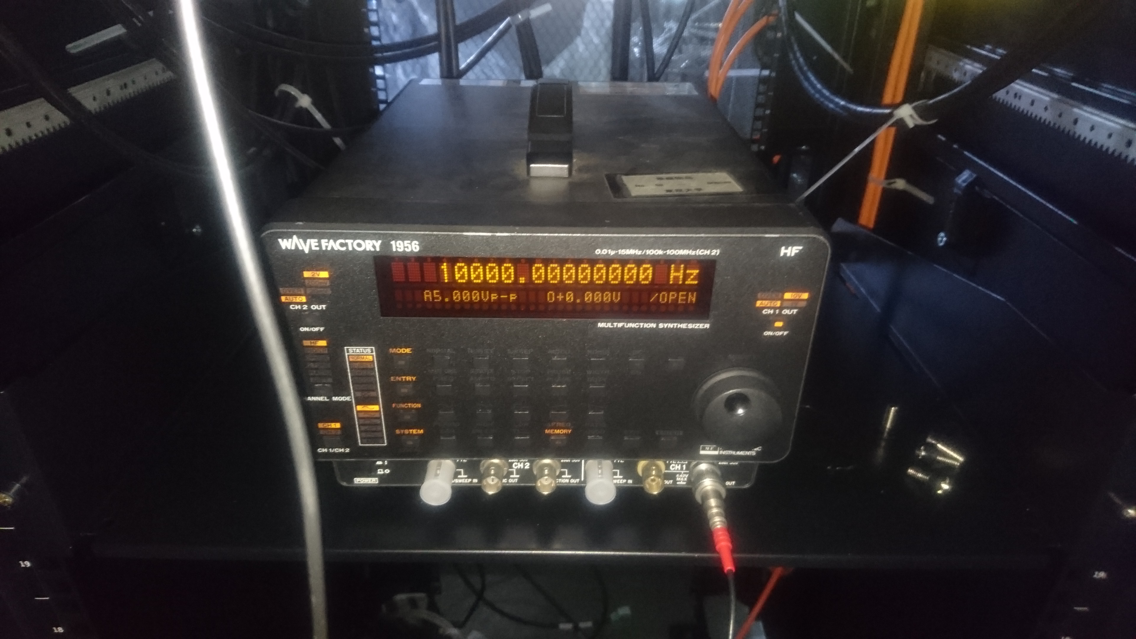
The setup of the function generator for LVDT modulation/demodulation is shown in the attached picture (frequency 10 kHz, Amplitude 5 Vpp.)
