Reports 1-1 of 1 Clear search Modify search
AOS (Beam Reducing Telescopes)
koji.nagano - 1:43 Friday 28 September 2018 (6334) Print this report
TMSX-VIS cable installation and signal checking

[K. Nagano, Hasegawa, K. Tanaka, Kita, Akutsu, Uraguchi with help from T. Yamamoto, Miyamoto]

Today, we finished to install all signal Dsub cables between EX0 and TMSX rack (with help from Tamori-san and Yochimura-san).

Then, we checked signals from TMSX-VIS sensors, three geophones and three LVDTs.
During this work we found that ADC1 and ADC2 which is new one (klog6210) were flipped (This was suggestted by Yamamoto-san.).
(ADC0 was properly working.)
To treat this flipping problem, we modifed RT model (k1vistmsx) and flipped ADC1 and ADC2 in the model.
Note that, in the real world, we did nothing except for label modification.
In other words, newly installed ADC is ADC"1" currently and old one is ADC"2".
In addition, we found that,  in the MEDM screen, master switch button did not work.
Miyamoto-san kindly fixed this problem.

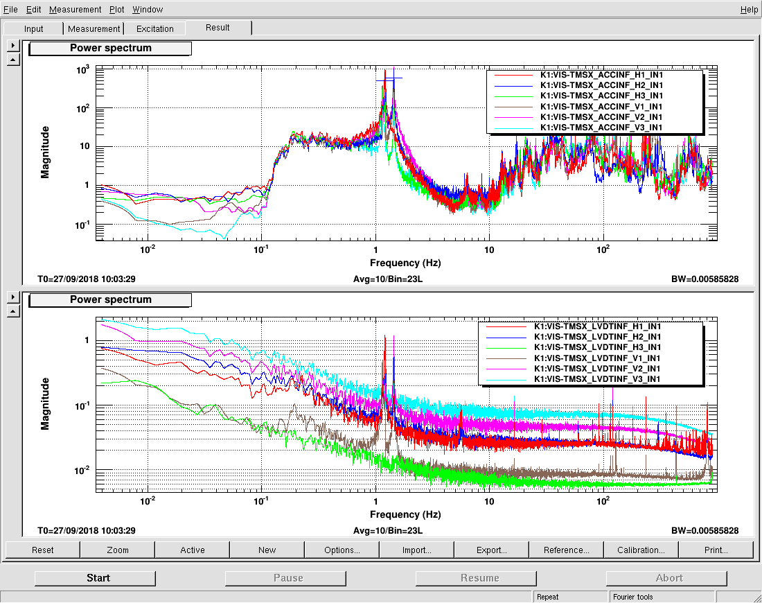
After all, we confirmed that signals from TMS-VIS were properly taken in digital system as shown in the attached figure.
The peaks at 1.2 Hz and 1.4 Hz may come from horizontal and vertical resonance of the suspended stage.
Note that the y-axis is NOT calibrated to physical value from deigital counts.

More detailed report about the above works will be posted later.

Images attached to this report
Comments to this report:
koji.nagano - 19:23 Sunday 30 September 2018 (6351) Print this report
Supplementary Explanation
 
# Cable installation
We assigned TMS channels as follows,
 
ADC1
Port Number #1 #2 #3 #4 #5 #6 #7 #8
Channel LVDT V LVDT H Geophone V Geophone H IR QPD1 IR QPD2 GR QPD1 GR QPD2

ADC0

Port Number #5 #6 #7 #8
Channel Misc 1 Misc 2 OpLev QPD IR/GR PD

DAC0

Port Number #4
Channel LVDT H

Not assigned yet: LVDT V (DAC)

Note1: V and H means vertical and horizontal, respectively.
Note2: Misc 1 and 2 in ADC0 are just spares and are not connected to anything in RT model for now.
Note3: Since we did not have usable port in DAC in this moment, we could not assigne actuation channel for LVDT Vcrying.

During this work, we found that there were no fasten metal (TOME KANAGU) in DAC0 port #4.
We should install it.

# Signal checking
At first, we could not see any signal in LVDT H3 due to the same reason as reported in klog5462.
We struggled to solve this problem and found that LVDT H3 signal could be seen in the same cable connection during test in NAOJ.
(In fact, we would to avoid the same setup since in the setup cable should be crossed. However, we could not found good solution. Thus, we just copied NAOJ's test setup.)

The setup of the function generator for LVDT modulation/demodulation is shown in the attached picture (frequency 10 kHz, Amplitude 5 Vpp.)

Images attached to this comment
Search Help
×

Warning

×