Reports 1-1 of 1 Clear search Modify search
VIS (BS)
eleonora.capocasa - 22:32 Thursday 22 March 2018 (4518) Print this report
Diagonalization of BS IM sensing: preliminary measurements

[ELEONORA, IZUMI, ASO, SHODA]

 
We are trying to diagnalize the sensing of the BS intermediate mass and possibly to develop a reliable procedure to apply to other suspensions.
 
We have 6 OSEM (3 veritical and 3 orizontal) and their signals are combined to reconstruct the motion of the mass in its 6 DOFs.
(We don't have any Oplev to be used as reference in this case.)
 
1) We have measured the auto-transfer function for all the DOFs in order to individuate their normal modes. (First plot in the attachment.) 
 
2) We have measured the cross-transfer function from each DOF with the others. If a cross transfer function shows a peak which only belongs to the DOF that is being excited we assumed that it is due to a coupling in the sensing. (See plots from 2 to 7 in the attachment.)
 
3) Comparing the amplitude of the the peaks we estimated the amout of sensing coupling between each combination of DOF.
 
4) We can now write a sensing matrix (with the off-diagonal elements we have measured) and use its inverse to diagonalize the sensing. (STILL TO BE DONE..)


Some issues found:

 
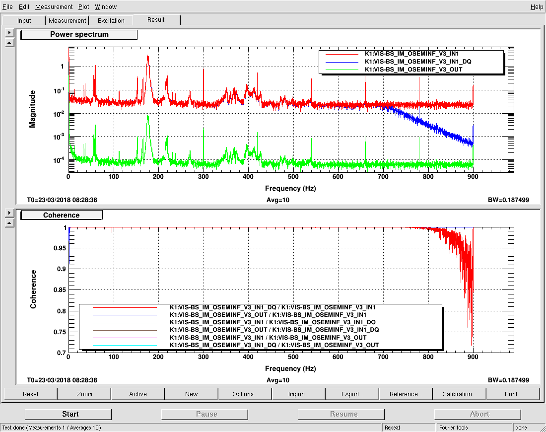
1) As a first check, I measured the open loop spectra for all the DOFs and for all the 6 sensors (plots 8 and 9 in the attachment).  I have notice that V3 as a quite large noise. It didn’t seem to affect the reconstruceted signals, but it looks very strange. 
 
2) When I excite the vertical motion I get larger signal in roll than in the vertical itself. (See plot 5). This is indeed very stange. More investingation has to be done. 
 
3) Also pitch shows a large couplig (more than 30%) with Roll.
 
3) The off-diagonal elements of the sensing matrix are not symmetric. It means that the amount of sensing coupling that I measure when I excite, for example, pitch and look at yaw is not the same if I do the other way round. I cannot imagine a configuration that brings to this asymmetry but maybe it is reasonable?
 
4) Longitudinal and Tranverse TFs are degenerated (as it should be ) and also their normal modes coincides with those of others DOF so this is difficult to apply this diagonalization technique to them. Probably is fine to leave them as they are.
 
 
The data of the TFs have been saved in .xml files in the folder  /users/eleonora/TF_BS_IM
Non-image files attached to this report
Comments to this report:
mark.barton - 3:05 Friday 23 March 2018 (4524) Print this report

Thanks for tackling this. Note that the matrix elements used are derived in T1707205. They're not expected to be symmetrical. They contain lever-arm information, so that if the output of the OSEMINF block is flag positions in µm, the output of OSEM2EUL should be in µm and µrad. The EUL2OSEM matrix is supposed to be the transpose of OSEM2EUL (this is the convention used at LIGO but note that Type Bp used a different, simpler convention).

ayaka.shoda - 15:36 Friday 23 March 2018 (4528) Print this report

We found that the strange spectrum is caused by the DQ system, not OSEM itself!

See attached figure of spectra. Even though **_IN1 and **_IN1_DQ are supposed to be the same, the spectra look very different.
And There is no coherence between IN1 and IN1_DQ.

Also, we could find sharp line noises at OUT signals, even though we have just anti-dewhitening filter and gain filter between the IN1 and OUT. These line noise is also observed at other signals.

Images attached to this comment
kiwamu.izumi - 16:33 Friday 23 March 2018 (4531) Print this report

Hey Shoda-san,

The fact that the OUT signals are suffering from some line noise makes me think this is not only an issue of the data acquisition system, but also some data processing issues in the real time model.

Can someone check whether the realtime model is healthy or not?

If this distorsion in the OUT signals is real, none of our control loops are healthy, including the BS optical lever loop which has been recently acting up (4520). 

takahiro.yamamoto - 18:12 Friday 23 March 2018 (4533) Print this report

I fixed this problem by restarting k1visbs.


At the beginnig, CFC in STATEWORD was turnd yellow,

DC status becomes "0x2000",

and the message "Modified File Detected" was displayed on DAQ LOAD(see attachement 1).


This means the real-time model is not rebooted after someone executed "make install-k1xxx".

So installed channel list is conflict with one used by a running model.


The spectra of *_IN1 and *_IN1_DAQ looks like same behavior (see attachement 2).

The harmonics of 16Hz also disppears.


Please check whether the problem is resolved.

Images attached to this comment
yutaro.enomoto - 10:23 Monday 26 March 2018 (4537) Print this report

= Now oplev loop for BS is properly working =cool

After the fix reported here (4533), I checked the behavior of the oplev loop of BS and found it is working.
It is working properly for more than 30 mins.
Procedure of turning on the filter was:
1. adjust offset in BS_TM_OPLEV_SERVO_{P|Y} so that the output of the filter will be small
2. press CLEAR HISTORY buttons
3. turn them on

This is probably due to restarting k1visbs (4533), though this fix should be related only to DAQ system.

yutaro.enomoto - 17:38 Monday 26 March 2018 (4541) Print this report

I forgot to write down the 4th step:
4. got the offsets gradually back to the original values so that we can set BS angle to the target.

Search Help
×

Warning

×