[Aritomi, Nakano]
Balancing efficiency of each segment of QPDA1,2 RF signal
We injected excitation from local oscillator (13.78 MHz) into test input of QPDA1,2 and tuned phase rotation of each segment so that only I phase signal appeared.
Then we tuned gain of each segment to balance the I phase signal.
Tuning sensor segment to PIT/YAW matrix
We excited pitch and yaw motion of MCi at 8 Hz and checked the relative phase of each segment and decided sign of elements of the matrix.
Then we tuned the absolute value of the elemetns to match transfer function of each segment.
We excited pitch and yaw motion of MCi at 8 Hz and checked the relative phase of each segment and decided sign of elements of the matrix.
Then we tuned the absolute value of the elemetns to match transfer function of each segment.
We excited pitch and yaw motion of MCi at 8 Hz and checked the relative phase of each segment and decided sign of elements of the matrix.
Then we tuned the absolute value of the elements to match transfer function of each segment.
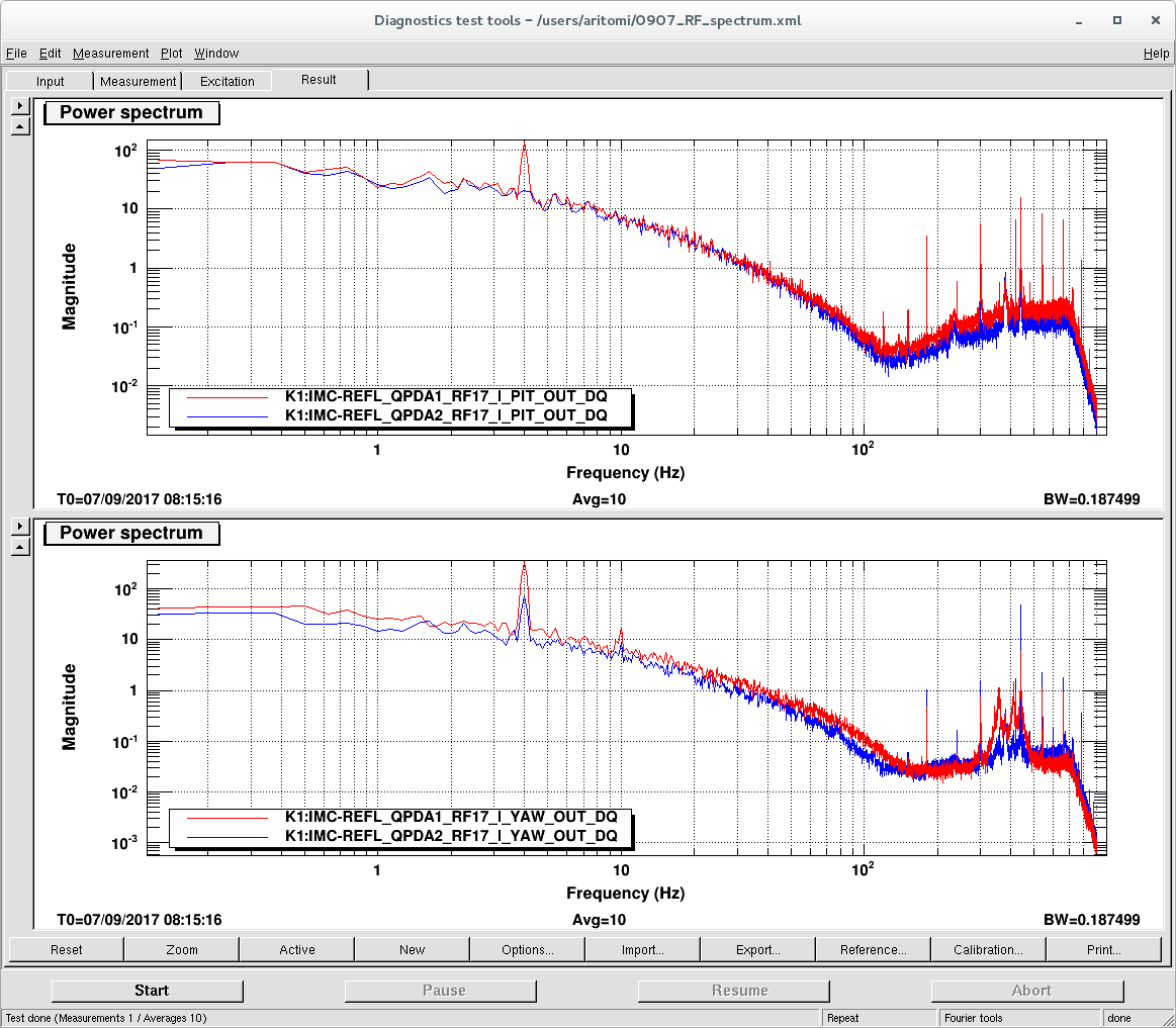
After these tunings, we excited yaw motion of MCo at 4 Hz (amp: 1000) and measured I phase signal of QPDA1,2.
The result is shown in the attached figure. Peak at 4 Hz became larger compared with the previous result (amp: ~10000).
Then we tuned the absolute value of the elemetns to match transfer function of each segment.
Then we tuned gain of each segment to balance the I phase signal.
We injected excitation from local oscillator (13.78 MHz) into test input of QPDA1,2 and tuned phase rotation of each segment so that only I phase signal appeared.
Then we tuned gain of each segment to balance the I phase signal.
We injected excitation from local oscillator (13.78 MHz) into test input of QPDA1,2 and tuned phase rotation of each segment so that only I phase signal appeared.
Then we tuned gain of each segment to balance the I phase signal.We injected excitation from local oscillator (13.78 MHz) into test input of QPDA1,2 and tuned phase rotation of each segment so that only I phase signal appeared.
Then we tuned gain of each segment to balance the I phase signal.
We injected excitation from local oscillator (13.78 MHz) into test input of QPDA1,2 and tuned phase rotation of each segment so that only I phase signal appeared.
Then we tuned gain of each segment to balance the I phase signal.
We injected excitation from local oscillator (13.78 MHz) into test input of QPDA1,2 and tuned phase rotation of each segment so that only I phase signal appeared.
Then we tuned gain of each segment to balance the I phase signal.We injected excitation from local oscillator (13.78 MHz) into test input of QPDA1,2 and tuned phase rotation of each segment so that only I phase signal appeared.
Then we tuned gain of each segment to balance the I phase signal.
We injected excitation from local oscillator (13.78 MHz) into test input of QPDA1,2 and tuned phase rotation of each segment so that only I phase signal appeared.
Then we tuned gain of each segment to balance the I phase signal.
Balancing efficiency of each segment of QPDA1,2 RF signal
We injected excitation from local oscillator (13.78 MHz) into test input of QPDA1,2 and tuned phase rotation of each segment so that only I phase signal appeared.
Then we tuned gain of each segment to balance the I phase signal.
Tuning sensor segment to PIT/YAW matrix
We excited pitch and yaw motion of MCi at 8 Hz and checked the relative phase of each segment and decided sign of elements of the matrix.
Then we tuned the absolute value of the elemetns to match transfer function of each segment.
After these tunings, we excited yaw motion of MCo at 4Hz (amp: 1000) and measured I phase signal of QPDA1,2. The result is shown in the attached figure. Peak at 4 Hz got larger compared with the previous result (amp:~10000).