[S. Nagano, Kokeyama, Nakano, Nogai (Niigata Univ.), K. Nagano]
This is a report on the IMC WSF work in this week.
Abstract
The aim of this work was make IMC WFS signals online.
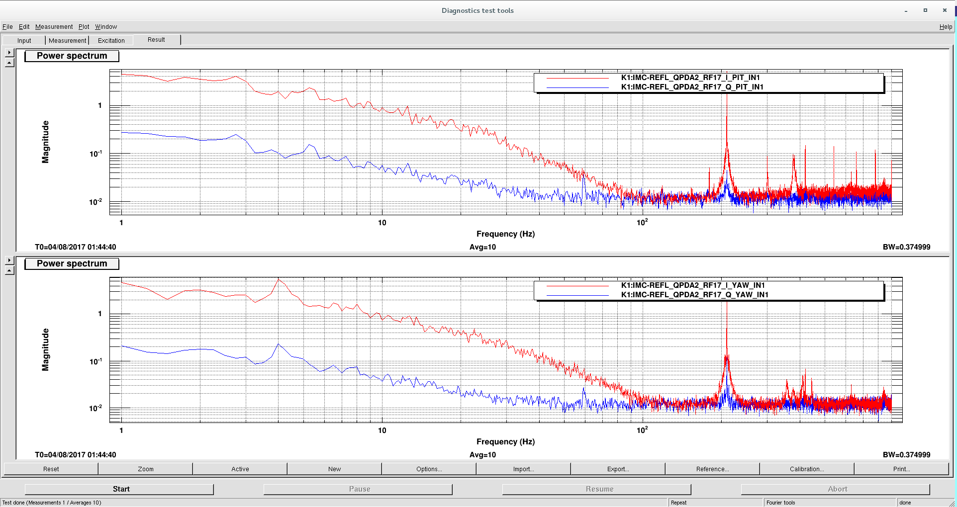
After we did what are listed as follows, the IMC WFS signals could be seen as shown in the attached figure.
In this test, MCo was excited at 4 Hz in yaw direction and its motion can be seen as a peak at 4 Hz.
What we did
1. Installed an RF distribution amp. into IOO rack
In the original setup, LOs for I&Q demodulator for ASC were provided with RF power splitter.
In order to increase error signals, we installed an RF distribution amp. and it is used to input LOs for WFS.
2. Increased laser power
To get larger signal, laser power was increased to 20 mW from 2 mW.
According to this power increase, we had to change setup of FSS loop as reported.
3. Changed used ADC card and realtime model
Originally, ADC2 card was mainly used in IMC ASC.
However, we found that the this card had high ADC noise as reported.
Thus, we changed used ADC card to ADC3 from ADC2.
This means that the output of AA which used to connected ADC2 is connected ADC3.
Please note that the ADC2 card was left as it was.
Related with this change, the realtime mode (IMCASC) was also updated.
4. Identified noise source in WFS signal
When we checked the IMC WFS signals after the above works, we found that the signals were very noisy below 100 Hz as shown in the aggtached figure.
(Above 100 Hz, the signals were mainly limited by ADC noise.)
To idendify the noise sources, we performed some switch-off and hammering tests.
As a result, we found that KOACH filter (and air flow) in PSL room induced low frequency noise.
In fact, when we switched off the KOACH filter at a moment, the noise leve decreased by a factor of from 5 to 10.
Although it is not clear how the KOACH filter affects the WFS sensitivity, we guess that air flow itself and/or the optical bench motion excited by the air flow might be a problem.
Thus, we may have to consider the wind whield of PSL and IMC REFL table.
The results of this test are summarized as follows:
-What has large effect:
--KOACH filter in PSL room (below 100 Hz)
--Air flow in PSL room (below 100 Hz, it happened when we opened or closed the door of PSL room or Zen-shitsu.)
-What has effect:
--Air flow on IMC REFL table (below 100 Hz, we excited air flow with a kind of fan.)
--Periscopes on PSL and IMC REFL tables (about 80 and 90 Hz and 380 and 410 Hz, we excited its motion by our hands)
--PSL optical bench (below 100 Hz, we excited its motion by our hands)
-What has almost no effect:
--IMC REFL optical bench
--Ref. Cav. motion (excited by hitting its chamber)
--Voice in PSL room
--Motions of optical components in IMC REFL table (lens, mirrors, and QPDs for IMC WFS)
--Motions of MCF chamber and the duct between PSL and MCF chamber excited by hitting them by our hands
5. Adjusted I&Q phase of each segment of RFQPDs
We adjusted I&Q phase of each segment of RFQPDs, seeing the signal at 40 Hz induced in FSS loop.
In this time, relative phase of I and Q was not adjusted, i.e. it is fixed at 90 deg.
Result
After all the above works, we checked if the IMC angle signal could be seen exciting tilt motions of IMC mirrors.
As aresult, the signal could be seen as shown in the attached figure.
As we said, MCo was excited at 4 Hz in yaw direction In this test.
The 210 Hz signal in the figure corresponds to the clibration line in FSS loop, i.e. the coupling with the frequency noise.
The coupling could be reduced by adjusting the sensing efficiency of each segment of the RFQPDS.
Next steps
The sensing efficiency of each segment will be balanced.
The sensing matrix wil be measured.
The filter shape of ASC will be considered.