[Akutsu, Tanioka]
In Mitaka (June 27).
1.Configuration
We applied DC voltage to the coil by using function generator.
When an electric current flows, a vertical force acts on the coil.
The mettler can measure how large this force is.
We have to take consideration into the displayed voltage may differ from the actual input voltage.
This is because the input/output impedance may not match.
2.What we did
Today, we measured how the force changed by changing the voltage in order to confirm that the coil functions properly.
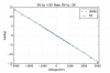
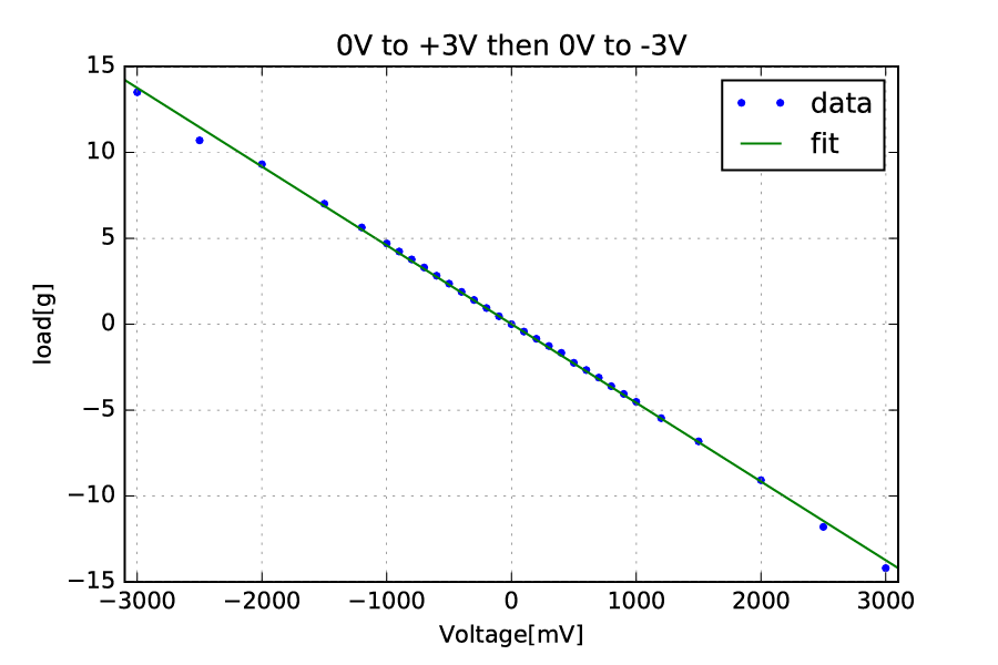
a.At first we change the voltage from 0 V to +3 V and then 0 V to -3 V.
We fitted the data with a straight line.
Around +/-3 V, the measured data seemed out of linear relation and the number of data was not sufficient.
So we decided to measure every 100 mV.
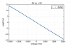
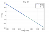
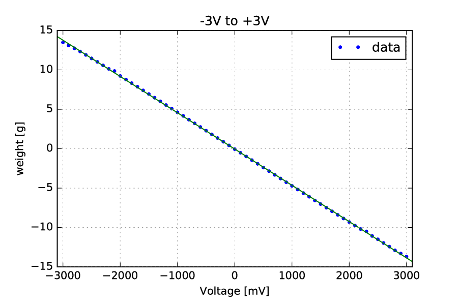
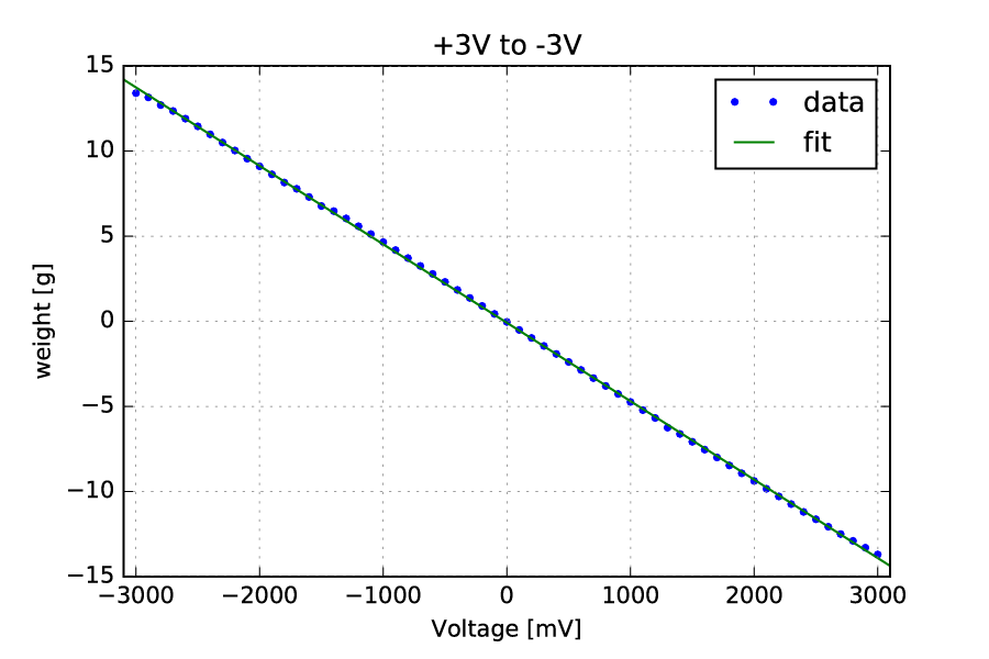
b.Second, we changed the voltage from -3 V to + 3 V and sweep to -3 V (back again).
Each data was fitted separately.
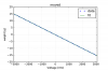
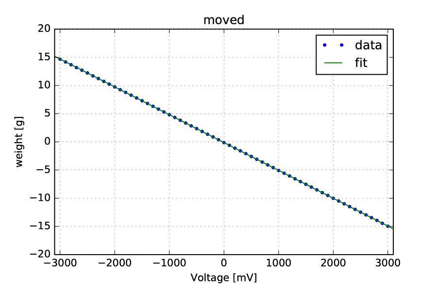
c.Finally, we changed the position of the magnet in the horizontal direction to check the tolerance (how large error from nominal is acceptable).
Also we changed the voltage to measure the behavior of force at the changed position.
tolerance +/- 3.5 mm
When we moved the magnet by 3.5 mm or more, the force increased rapidly.
3.Results
slope of the line
(The alphabet corresponds to the above one.)
a.-4.6 g/V
b.-4.6 g/V (-3 V to +3 V)
-4.6 g/V (+3 V to -3 V)
c.-4.9 g/V (2 mm moved horizontally from the nominal position)
When the position changes, the slop became steeper.
So the displacement may affect the performance of the actuator.
The attached figure shows the measured and fitted data.