Reports 1-1 of 1 Clear search Modify search
AOS (General)
tomotada.akutsu - 12:41 Saturday 24 June 2017 (2994) Print this report
Test setup of a coil-magnet actuator for TMS stage

[Tanioka, Morozumi, Akutsu]

In Mitaka (2017 June 22).

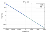
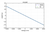
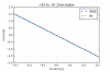
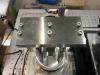
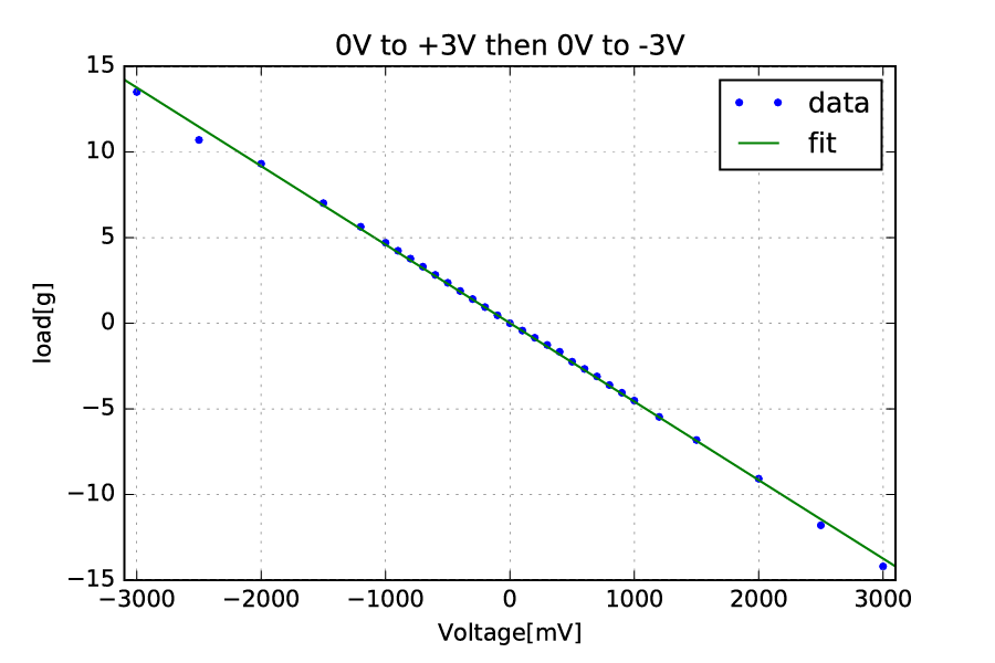
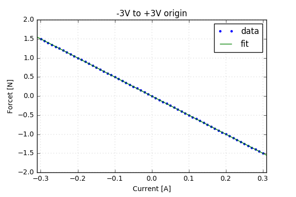
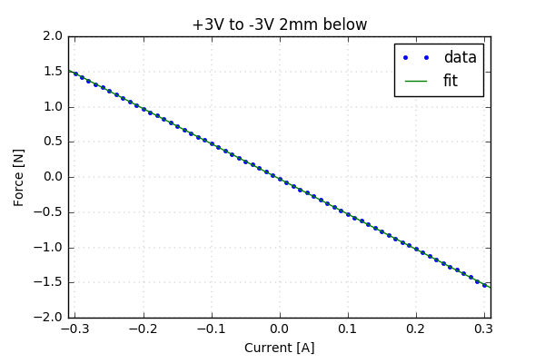
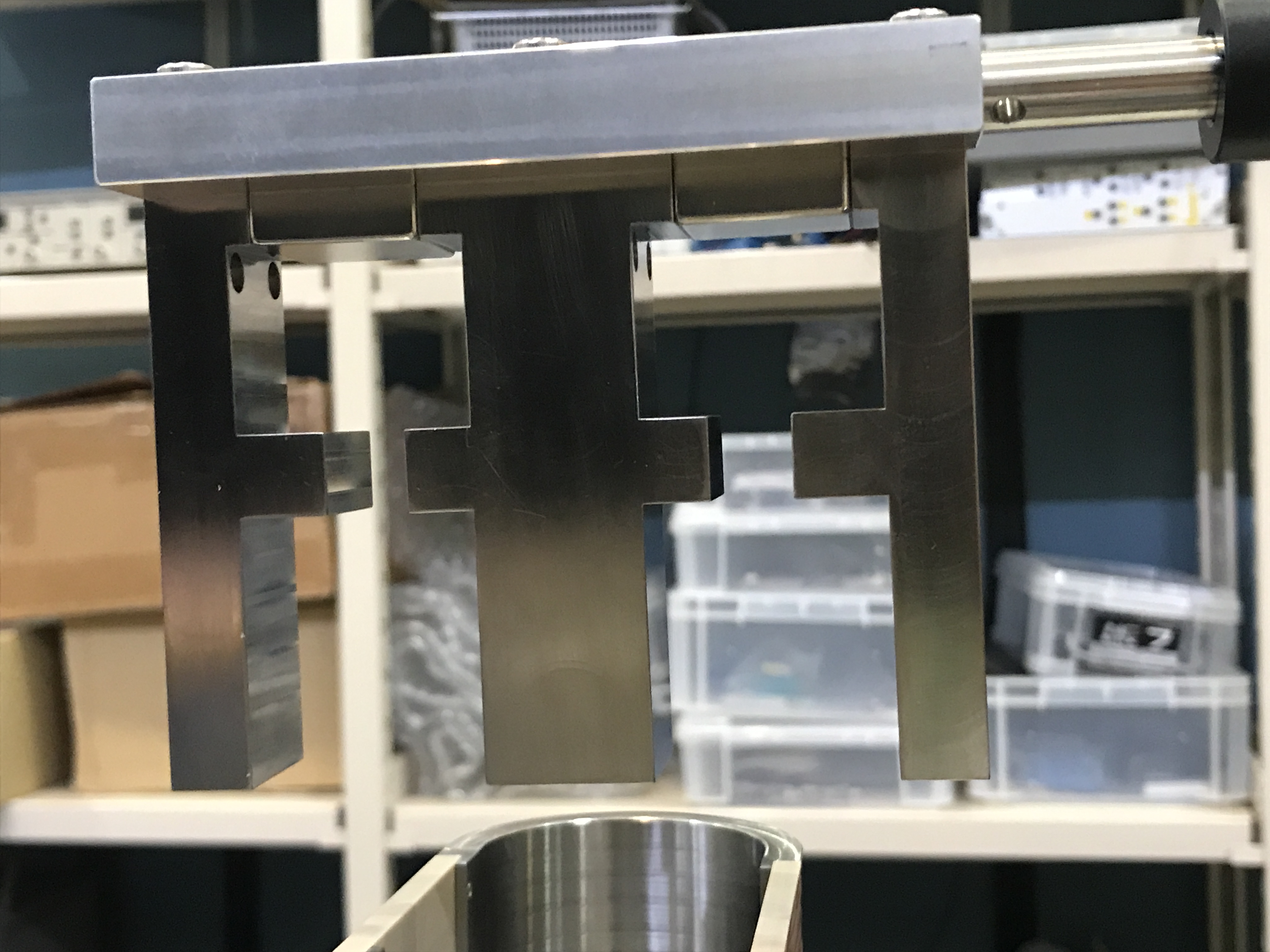
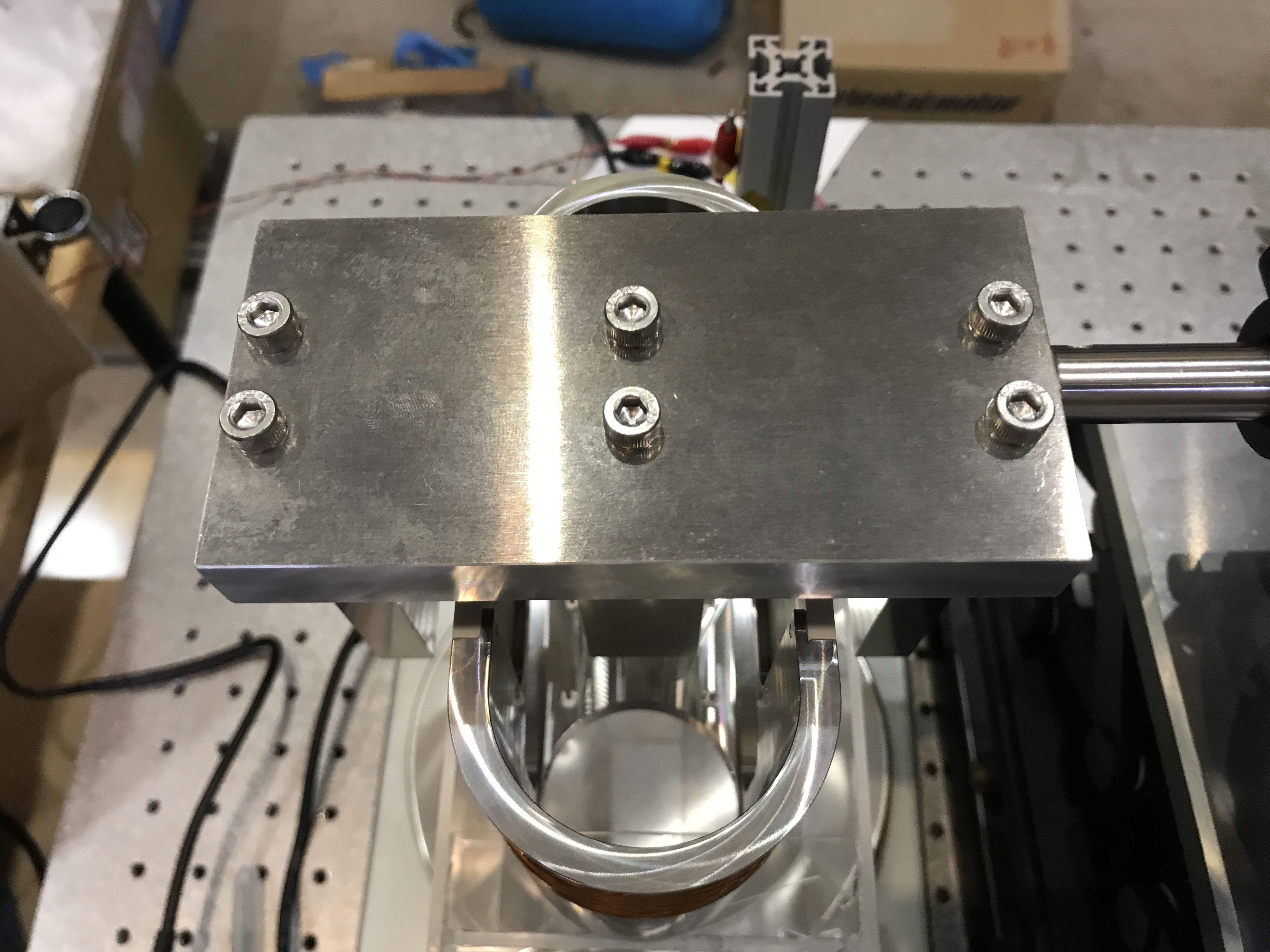
The KAGRA transmission monitor system (TMS) will be put on a vibration isolation stage in the future. The stage will have active control, and so we are developping some local sensors and actuators. We made a testbench to check the local actutator (coil magnet one) in Mitaka.

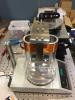
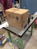
The coil part is put on a metler with a plastic leg, which makes a distance beween the sensitive dish of the metler and the coil/magnet part so that the sensitive dish won't get fake signals from the magnetic field. The the metler part was covered by a carton box so that air flow does not fluctuate the measurement. Now the output signal get stable. After connecting the coil wires to a driver with a adapter cable, we zerod the readout (tuned the offset). We are ready...

Images attached to this report
Comments to this report:
satoshi.tanioka - 1:09 Wednesday 28 June 2017 (3009) Print this report

[Akutsu, Tanioka]

In Mitaka (June 27).

1.Configuration
We applied DC voltage to the coil by using function generator.
When an electric current flows, a vertical force acts on the coil.
The mettler can measure how large this force is.

We have to take consideration into the displayed voltage may differ from the actual input voltage.
This is because the input/output impedance may not match.

2.What we did
Today, we measured how the force changed by changing the voltage in order to confirm that the coil functions properly.
a.At first we change the voltage from 0 V to +3 V and then 0 V to -3 V.
We fitted the data with a straight line.
Around +/-3 V, the measured data seemed out of linear relation and the number of data was not sufficient.
So we decided to measure every 100 mV.

b.Second, we changed the voltage from -3 V to + 3 V and sweep to -3 V (back again).
Each data was fitted separately.

c.Finally, we changed the position of the magnet in the horizontal direction to check the tolerance (how large error from nominal is acceptable).
Also we changed the voltage to measure the behavior of force at the changed position.

tolerance +/- 3.5 mm
When we moved the magnet by 3.5 mm or more, the force increased rapidly.

3.Results
slope of the line
(The alphabet corresponds to the above one.)
a.-4.6 g/V
b.-4.6 g/V (-3 V to +3 V)
-4.6 g/V (+3 V to -3 V)
c.-4.9 g/V (2 mm moved horizontally from the nominal position)

When the position changes, the slop became steeper.
So the displacement may affect the performance of the actuator.

The attached figure shows the measured and fitted data.
Images attached to this comment
satoshi.tanioka - 21:50 Monday 17 July 2017 (3103) Print this report

In Mitaka.

I measured the efficiency of coil magnet actuator as same manner as I did before. The signal was generated by the signal generator which has 50 ohm input impedance. First, I adjusted position to set the magnet at center. Then, I changed the position of the magnet. I moved to right side and back side as seen from the front of the mettler and lowered the magnet downwards. When I moved the magnet, zero point (the value when the current is 0A) varied.

[Measured position]
・original
・1mm to right
・1mm to right and 1mm to back
・2mm to right and 1mm to back
・2mm to right and 2mm to back
・1mm below
・2mm below

[Result]
・the efficiency(slope of fitted line)
The efficiency was all the same value.
-5.0 N/A
No change due to changing position was seen.
This value is larger than I measured before (-4.5 N/A).

・offset value (the unit is not [N])
original 0.01g -0.03g
1mm to right and 1mm to back -0.05g -0.06g
2mm to right and 1mm to back -0.07g -0.08g
2mm to right and 2mm to back -0.06g -0.08g
1mm to right 0.06g 0.06g
1mm below -0.13g -0.13g
2mm below -0.25g -0.26g
Left value is when the voltage was changed -3V to 3V, right value is when the voltage was changed 3V to -3V.

When I moved the magnet below, the offset value varied. However, the efficiency did not change.


The change of the efficiency was seen when I measured before, but it could not be seen this time. Moreover, the efficiency was about 10% larger than before.

The attached figure shows the measured and fitted data of original(initial) position and when I lowered the magnet (the offset is different slightly). Other point was almost the same as initial position.

Images attached to this comment
satoshi.tanioka - 19:00 Monday 04 September 2017 (3323) Print this report

in Mitaka

I measured the magnetic flux of a prototype coil magnet actuator for TMS vibration isolation system.
I used a tesla meter "MODELbTM-801" by KANETEC.
The magnets made by Neo Mag were used and the magnetic flux of this magnet was about 556 mT.

[Result]
The magnetic flux inside the yoke (overhang part) was about 115 mT.
This value is smaller than the designed value about 170 mT.
The difference seems to be leakage of flux.

Then I measured leakage of the magnetic flux from the surface.

upper surface
Measured at 3 points (screw position)
left & right side was about 13 mT (magnetic pole:S).
center was about 28 mT (N).
There were zero cross position about 2.3 mm from the side edge.

The leakage from bottom surface were about 35 mT (S) both left and right.
This value was measured around the center of surface.
At the edge, the flux was much larger about 80 mT.

The detail will be uploaded to JGWdoc.

Anyway, the magnet flux inside the yoke were smaller than designed.
This is caused by leakage from other surface and this leads to the less efficiency of the actuator.


The estimated efficiency is 6.95 N/A, however, the actual value is 5.0 N/A.

Images attached to this comment
tomotada.akutsu - 21:07 Monday 04 September 2017 (3326) Print this report

Thanks very much!

Search Help
×

Warning

×