[Nakano, Kokeyama, Shimoda]
Today we locked IMC again and measured some parameters. What we did and their results are as follows:
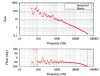
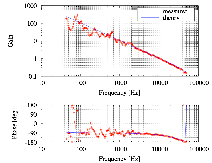
1. Open loop gain under low-Finesse(p-polarization input) : UGF=10kHz
We measured OLG under low-finesse lock (feedback to laser PZT only). The result is shown in the first attatched file. The measured OLG agrees with expected one(blue line in the file) very well. Estimated delay time from phase fitting was 3.1us.
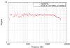
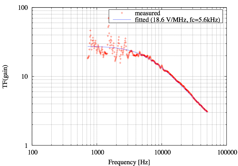
2. Optical gain of IMC with low-Finesse (p-polarization input) : 3.24 V/MHz (cavity pole=65kHz)
We injected excitation signal into Common Mode Servo and measured transfer function from SLOW OUT to demodulated error signal of REFL RFPD. The result is shown in the second attatched file. It corresponds to (actuator efficiency of laser PZT)*(optical gain) and we already have actuator efficiency 1.48 MHz/V. Then optical gain and cavity pole was estimated by fitting it.
3. Actuator efficiency of MCe suspension : 25.5 MHz/V @DC
We excited MCe suspension at 40Hz and measured transfer from the excitation signal to demodulated error signal of REFL RFPD (without feedback to suspension). The measured value correspond to (actuator efficiency of suspension) * (optical gain) / ( 1 + OLG ) at 40Hz. By using optical gain and OLG measured above, the actuator efficiency at 40Hz was calculated (15.9 kHz/V @40Hz), then extrapolated to DC by assuming the resonant frequency of the suspension is 1Hz.
4. feedback to suspension of MCe
In addition to laser PZT feedback, we tried feedback to MCe suspension. The expected cross-over between laser PZT feedback loop and suspension feedback loop was around 10Hz and measured cross-over was about 15Hz, so feedback to suspension seems working well.
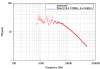
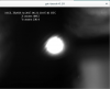
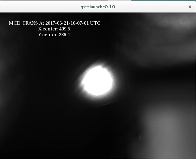
5. Locked IMC with high-Finesse(s-polarization input)! Optical gain : 18.6 V/MHz (cavity pole=5.6kHz)
At the end of today, we changed the polarization of the output laser from p to s, and locked IMC again. Then we measured optical gain again. Measurement method was same as 2.(low-finesse optical gain). The result is shown in the third file. At this time, the amplitude of error signal was 99mVp-p. Screenshot of TRANS beam is attatched(fourth file).
concern : Today we flipped the sign of coil output filter for MCe H3 (K1:VIS-MCE_TM_COULOUTF_H3_Gain) from -1 to 1 because we couldn't push MCe Length. It had been set to -1 (since around klog2329?). Although now we can move MCe Length enough to find resonance, we have to investigate about sign of actuators again.