Reports 1-1 of 1 Clear search Modify search
VIS (PR3)
fabian.arellano - 22:15 Tuesday 20 April 2021 (16521) Print this report
Setting the mirror to nominal height

With Hirata-san.

See pictures in album PR3 Remedying Work.

The aim was to set the height of the mirror to nominal value.

First we corroborated the horizontal line drawn on white tape next to the +X side flange was Terada-san's height mark.

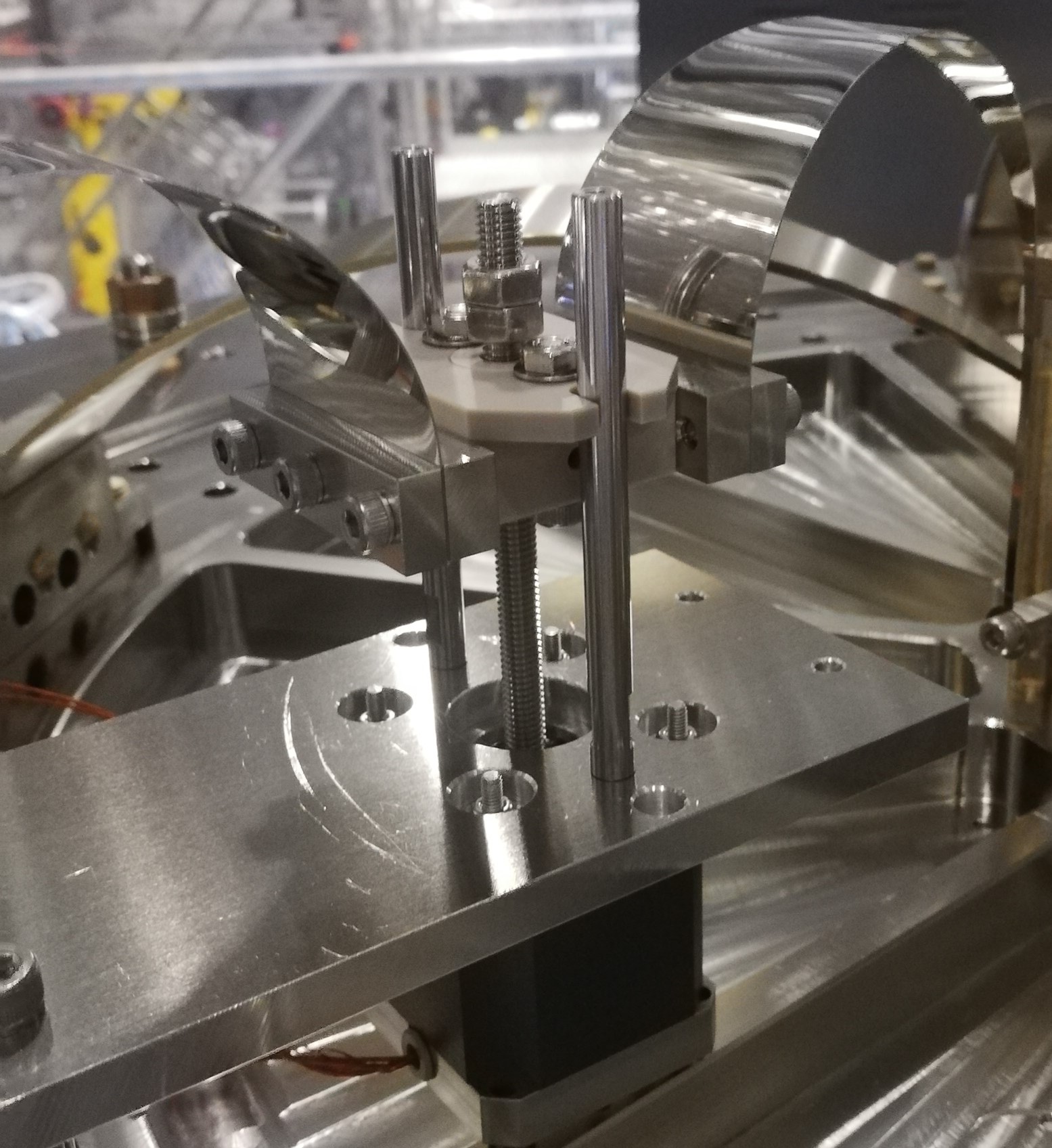
  • We taped a long ruler on the vacuum chamber as shown in this picture.
  • We set the laser level to the outermost edge of the flange. Such flange is 880 mm in diameter according to the 3D-CAD
  • We moved the laser level 440 mm down to the vertical centre of the flange and it coincided exactly with Terada-san's mark.

Then we proceeded to set the height of the mirror to nominal.

  • We locked the SF at nominal height per the 3D-CAD (65.5 mm from the base plate).
  • From visual inspection it seemed the RM was below the nominal height by more than 2 mm at one side.
  • The RM also has some roll.
  • We moved the BF keystone with the fishing rod up but the goal seemed to be out if its range.
  • Then we used 30,000 counts of actuation but it still required to go further up.

This situation deserves more consideration.

Comments to this report:
shinji.miyoki - 17:09 Wednesday 21 April 2021 (16532) Print this report

I found the temp increase from 20:00 on 20th around 16:00 on 21st after Fabian's notice. I suspected the stop of SR-C cooler. Yoshimura-san found it actually stopped, then he restarted it. The stop reason was same as previous trouble.

fabian.arellano - 17:57 Wednesday 21 April 2021 (16529) Print this report

With Hirata-san.

See pictures in album PR3 Remedying Work.

  • We measured the height of the mirror assembly when the SF was at nominal height per the 3D-CAD (65.5 mm from base plate) and the BF was at the setpoint given in the medm screen.
    • The laser level was at the nominal height of the mirror.
    • -Y side picture: approximately 2.7 mm below nominal (by visual inspection with ruler).
    • +Y side picture: approximately 1.7 mm below nominal.
    • Note there is certain amount of roll revealed by the 1 mm difference between the two sides.
  • The mirror has scribe marks on the cylindrical part showing the vertical mid-plane. One of them seemed to be below the laser level by the same amount as the mark in the RM, but it was impossible to check with a ruler. 
  • We also used the vernier calliper the size of the buoyancy correction in the SF by setting the keystone in the positions it was before and after the venting according to entry 16445. We did it because we were not sure whether there had been any problem with the LVDT card. We measured 460 µm and the measured LVDT value was 585 µm, which is close enough taking into account possible errors in measuring with the calliper today.
  • Then we moved the SF keystone up with the fishing rod until the mirror asembly was at the nominal height (see pictures of the day in the album):
    • The fishing rod reached its upper limit. See this picture, which is also attached to this report. This is a very inconvenient situation.
    • Additionally, the keystone has to move even further up in order to take into account the buoyancy correction
    • The temperature now is 24.7 °C, which is very high compared to the O3GK temperature 23.2 °C (entry 15816).

The last item suggests we need to move the fishing rod to mid-range and remove mass from the top of the BF to allow the SF go up to the suitable height. However, in order to assess the situation better we require to have the O3GK temperature. Now it's 1.5 °C higher.

Images attached to this comment
fabian.arellano - 17:25 Thursday 22 April 2021 (16546) Print this report

With Hirata-san.

See pictures in album PR3 Remedying Work.

The temperarture decreased after Miyoki-san and Yokozawa-san took action. When we went into the clean room it was already 23.6 °C. Becuase of this change we had to move the the BF and SF fishing rods down to set the keystones at suitable positions.

Then we measured the position of the SF keystone when the BF is at the setpoint and the mirror at the nominal height indicated by the laser level per the heigh mark on the chamber: it was -585 µm. This is about 705 µm above the value of the setpoint at the time. The setpoint must be changed to the new value.

We then checked the position of the SF fishing rod carriage. With the new temperature value it was far away from the upper limit, implying that we don't need to adjust the ballast mass from the top of the BF. Another element that helped in having the fishing rod in a suitable position, was that we corrected a systematic error in estimating the height of the mirror. The markings in the RM had to be compared with the bottom of the laser line, not with its centre as we did yesterday. The laser line has a thickness of roughly 2 mm as seen by bare eyes (the camera is more sensitive).

As an additional precaution, we moved the stop screws to the very top of the motor shaft as shown in this picture. Then we measured the fishing rod range with the LVDT:

  • Upper limit per LVDT:  2,116 µm at -550,000 steps.  See this picture.
  • Lower limit per LVDT:  -3,352 µm at 1,360,000 steps. See this picture.

Please note that I changed the stepper motor limits in the corresponding medm screen to the values above.

It's important to notice that the buoyancy effect is 585 µm (entry 16445) and we have plenty of fishing rod range to compensate for it.

At the end of the day I measured IM transfer functions. They looked fine. Then we locked the SF and covered it with a plastic sheet.

fabian.arellano - 17:42 Monday 31 May 2021 (16892) Print this report

I input into the medm screen the information about the suitable position of the SF in order to have the mirror at the appropriate height.

According to entry 16546, the suitable position of the SF is -585 µm and, as written in the medm screen, the calibration factor is 0.337 µm/cnt. This implies that the suitable position of the SF is -1736 cnt. This is, in order to have the SF LVDT readout equal to zero at such a position, before multiplying by the calibration factor, the original input must be offset by 1736 counts

  • I changed the offset in the LVDTINF filters and I also turned on the offset switch.
    • K1:VIS-PR3_SF_LVDTINF_GAS_OFFSET: 0 → 1736 counts
    •  K1:VIS-PR3_SF_LVDTINF_GAS: IN, OT, DC → IN, OF, OT, DC.
  • I changed the setpoint to zero:
    • K1:VIS-PR3_SF_SET_GAS_OFFSET: -1290 µm→ 0
  • I updated the SDF.
Images attached to this comment
Search Help
×

Warning

×