Reports 1-1 of 1 Clear search Modify search
VIS (EX)
fabian.arellano - 22:37 Wednesday 03 March 2021 (16142) Print this report
IP and F0 stepper motor limit switches.

With Hirata-san and Washimi-san.

Pictures and notebook notes at ETMX Remedying work.

  • We tested the IP limit switches by triggering them with an Allen key and seeing the output in the medm screen. They all worked well as expected.
  • We began the assembly of the F0 limit switch assembly. Unlke the Type-B IP tables, the one in the X End does have threaded holes where to fix the limit switch holder. See this picture and this other one.
  • We removed from the IP table the old F0 yaw stepper motor. The assembly weighed 385 g without the cables. See pictures.
  • We began the assembly of the new F0 yaw stepper motor with the limit switches.
Comments to this report:
fabian.arellano - 21:17 Thursday 04 March 2021 (16159) Print this report

With Hirata-san and Washimi-san.

Pictures and notebook notes at ETMX Remedying work.

  • We continued assembling of the F0 yaw stepper motor assembly.
  • We checked the polarity of the F0 fishing rod: it's incorrect, a negative number of steps moves the carriage up.
  • We hooked the suspension rod:
    • We had to move the keystone down by 32 mm in order to hook the nail head. To realize such a large displacement we couldn't use the current push-down screws, which are too short (M8×35mm). Instead, we used the long pull-up screws (M8×80mm) after we moved them to the pull-down places. See this picture.
    • The original height of the keystone, with respect to the upper security stop plate (wee this picture again), was 14 mm. We moved it down to 46 mm to hook it and the we moved it up to 36 mm to create tension in the rod without lifting the load.
  • In order to finish assembling the keystone assembly we need to put back the pull-up and push-down screws back to their respective places (see this picture), but we would need to lift the keystone by a lot and suspend the load of the filter. That work requires preparation of the lower stages and we didn't do it. This implies we can't install the F0 yaw stepper motor now.
satoru.ikeda - 17:12 Friday 05 March 2021 (16170) Print this report

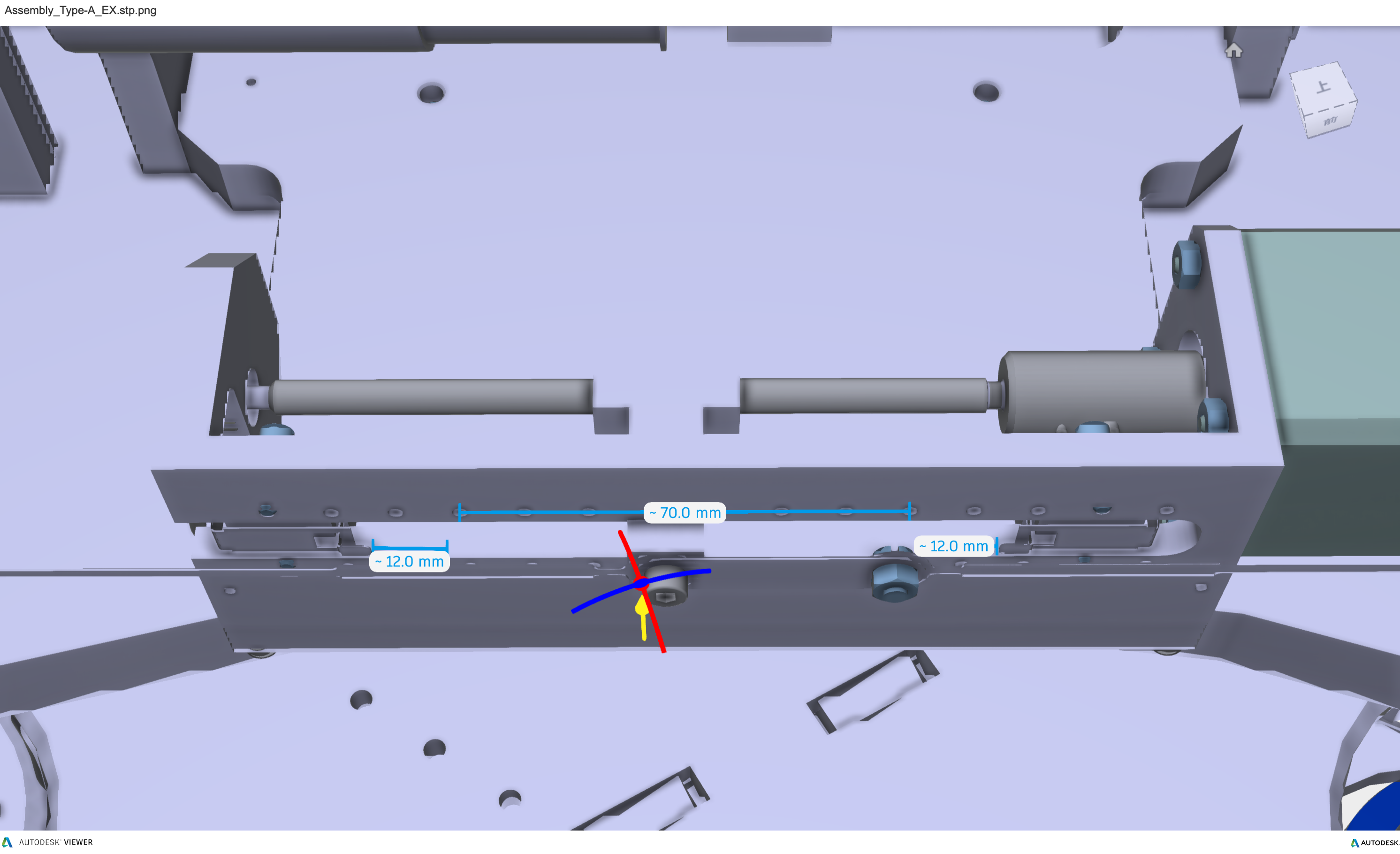
/Dropbox/Subsystems/VIS/TypeA/STEP/Assembly_TypeA_EX.stp
From the CAD data, I tried to figure out the drivable area of each IP of Type-A.
The distance between the screw holes is 10mm, so the actual position of the stepper motor is calculated from the screw holes based on this.

There is one point of difference between the CAD and the current situation.
The connection.strip that attaches the T-type drive part and FR spring is bolted to the left side in the CAD, but in reality it is on the right.

The driving part of the T-type stepper motor is 24mm wide, and the center of this width is the position of the motor.
From the above, the position of the motor can be moved up to 12mm from the limit switch.

From the CAD, the driveable area is from the 5th to the 12th position counting from the motor side.
Therefore, the drive range between the left and right limit switches is 70mm, but the drive range is limited to 90%, from 5.5 to 11.5.

Next, the current position of the stepper motor of the ETMX IP was the following value.

H1 -298,489[count].
H2 291,013[count].
H3 21,024[count].

The actual position is shown in the attached photo of K-Log#16159, counting the position of the holes from the motor side, and it is at the following position
Consider this as the current position of the motor.

H1 6.9 (=69[mm])
H2 9.8 (=98[mm])
H3 7.2 (=72[mm])

Since the drivable range is from 55[mm] to 115[mm] (5.5 to 11.5), we consider the distance to each position.

  to 55[mm] to 115[mm]
H1 -14[mm] +46[mm]
H2 -43[mm] +17[mm]
H3 -17[mm] +43[mm]

Calculate and set the drivable area of each motor from the distance.
Since 51,200[count]/M6 screw pitch 1[mm] per motor revolution, multiply the above and add it to the position of the stepper motor.

  Min Max
H1 -1015289 (=-298,489-14*51200)[count] 2056711 (=-298,489+46*51200)[count])
H2 -1910587 (=291,013-43*51200[count]) 1161413 (=291,013+17*51200[count])
H3 -849376 (= 21,024-17*51200[count]), 2222624 (=21,024+43*51200[count])


This is the software limit range.
After setting sitemap-STEPPING MOTOR-STEPPER_OVERVIEW-Limit Min[steps] and Limit Max[steps], write with [L].

Also, set the limit SW of ETMX IP-H1, H2 and H3 as effective.
sitemap-STEPPING MOTOR-STEPPER_OVERVIEW-LR Set 1 (enable) to Distance[steps or SW] and write with [D].
 

Images attached to this comment
Non-image files attached to this comment
fabian.arellano - 18:49 Sunday 07 March 2021 (16178) Print this report

Report for the work carried out on Friday 5th of march 2021.

With Hirata-san and Washimi-san.

Pictures and notebook notes at ETMX Remedying work.

  • The original polarity of the F0 fishing rod stepper motor was correct. We tested it again. I made a mistake and thought it wasn't. 
  • We tested the F0 fishing rod limit switches using the medm screen and pressing them with the finger. They worked well.
  • We finished putting together the F0 yaw stepper motor assembly, tested its polarity and the limit switches also. All is worked well as expected.
Search Help
×

Warning

×