----------------------------------- Summary -----------------------------------
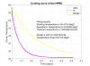
Attachment is a fitting plot for the cooling curve of the high power beam dump. The heat occurred at the dump is conducted from the dump to the copper flange through 10 copper heat sinks. The fitted thermal conductivity is 1300 W/m/K, where as the thermal conductivity of copper (heat sink) is 400 W/m/K around 30-60 deg C.
The result means that there are paths where the heat at the dump is conducted in addition to the heat sinks. Actually the additional heat path is the pedestal part of the dump made of SUS to the optical table. SUS has a lower thermal conductivity, but the area of the pedestal part was too big for our purpose, it turned out.
----------------------------- The fitting function T(t) ----------------------
By Fourier low of heat, a heat flow from a point i to j per sec, Q [W], can be express as
Q = -lamda * (Ti - Tj) * A / dx
where lambda is a thermal conductivity of the path, A is the area of the path, dx is the length of that path, and Ti and Tj are the temperatures, respectively. Assuming an equilibrium temperature of Ta and the thermal conductivity does not depend on the temperature (within our consideration),
M*C0 * dT(t)/dt = lambda * A / dx * (Ta - T(t))
where C0 is a specific heat and M is the weight of the heat sink. Solving the equation,
T(t) = Ta - (Ta - T(0)) * exp (- lambda * A / (dx*M*C0 ) * t)
Ta, T(0) and lambda are the fitted parameters in the plot.
I got the actual expected situation.
Another question is how much value did you use for A ( is the area of the path), and dx (is the length of that path)? They are belong to SUS rod property? or mesh wires ?
Situations of the thermal paths are explained in http://klog.icrr.u-tokyo.ac.jp/osl/?r=9238.
The new part of this measurement is that the measurement was done in vacuum for the first time. Although the thermal conductivity fitting is also new, this much larger number were something we expected.
I did also the simulation, assuming many parameters.
I considered 3 body connections, that are HPBD, aluminam plate where the HPBD is situated with a SUS pole that has finite length (0.105 m) and cross section (diameter ~ 5cm), and a copper plate that was connected with many thin aluminum wires (diameter ~ 500um, 300, length ~ 0.6m ) to HPBD. I also assumed the size of HPBD (~0.1 x 0.1 x 0.06 m ). These parameters are just assumption judged from photos.
The result can be same with the actual one as the attached file by adjusting parameters.
The most important tendency is that the temp increase of HPBD was almost dominated with SUS pole thermal conductance. If the thermal conductance of thin wires are getting more dominant, the speed of temp increase should become more moderate than the actual one. Even if no wires, the expected temp becomes ~ 3 C higher.
This is consistent with Kokeyama-san's conclusion.
So, if we reject heat conduction through SUS pole with ceramic or so, we need more ~ 10 times heat conduction through wires to keep HPBD temp less than ~ 100C. Is it realistic to increase the number of wires ? Do we need design improvement itself ?
----
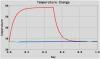
About simulation graph:
Red is the temp of HPBD,
time=0 day, 10W injection on HPBD,
time=0.5 day no injection on HPBD.