Reports 1-1 of 1 Clear search Modify search
PEM (Center)
chihiro.kozakai - 16:14 Saturday 22 February 2020 (13105) Print this report
Noise hunting around OMC, AS and SRM chamber

[Yokozawa, Washimi, Kozakai, Uchiyama, Saito, Miyoki, Oshino]


Summary:

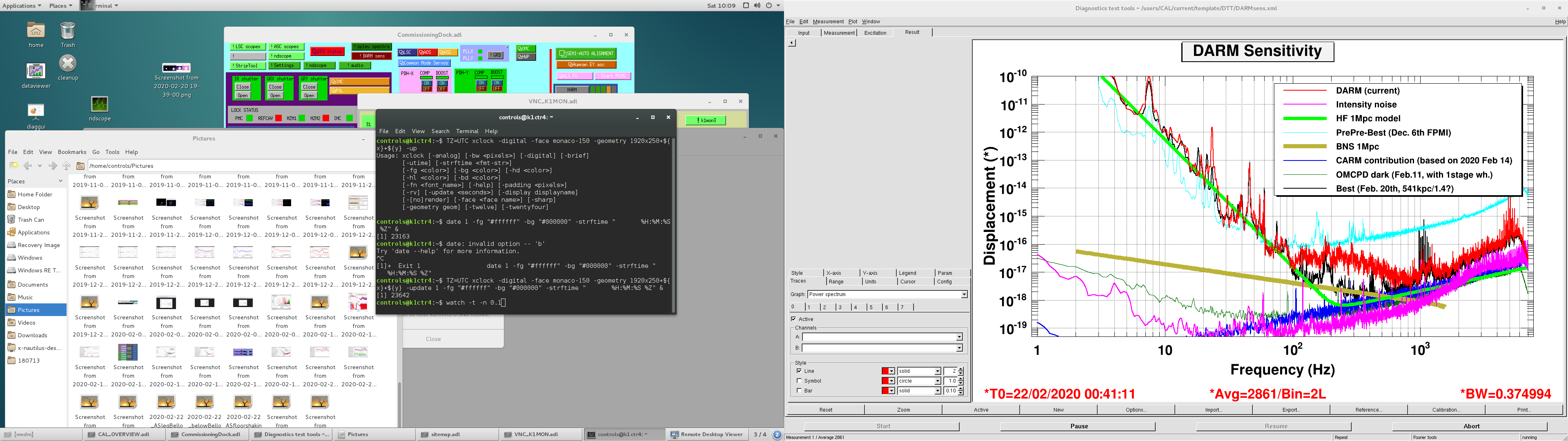
We did noise hunting around OMC, AS and SRM chamber. As Miyoki-san already posted,

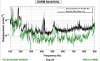
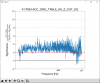
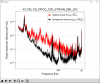
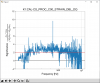
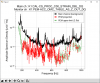
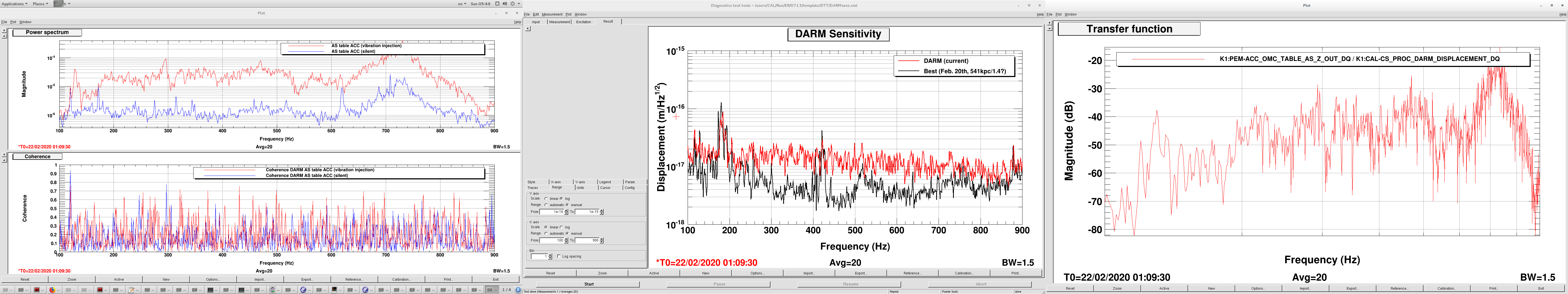
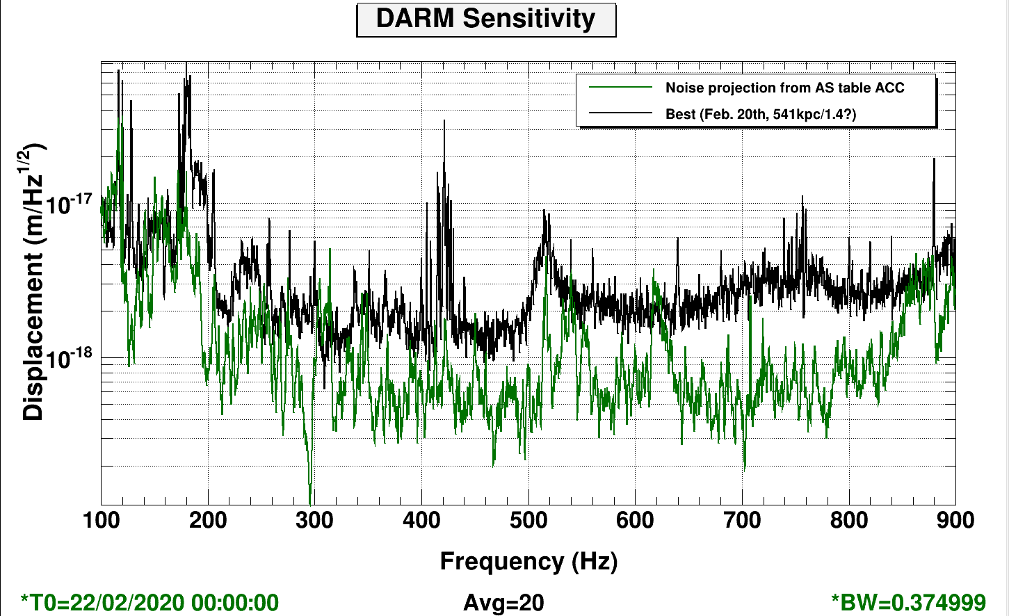
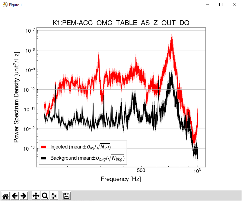
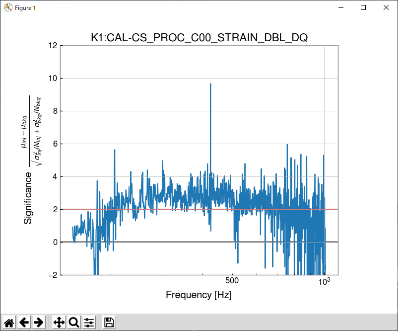
1) PEM team found strong correlation btw sensitivity and vibration around OMC around 100Hz ~ 400Hz and around 7-9 kHz .

This post attach some interesting data taken today.


Figures:

Fig. 1: The leg of AS chamber, bellows is shaked. Noise increased a lot and also lock loss happened.

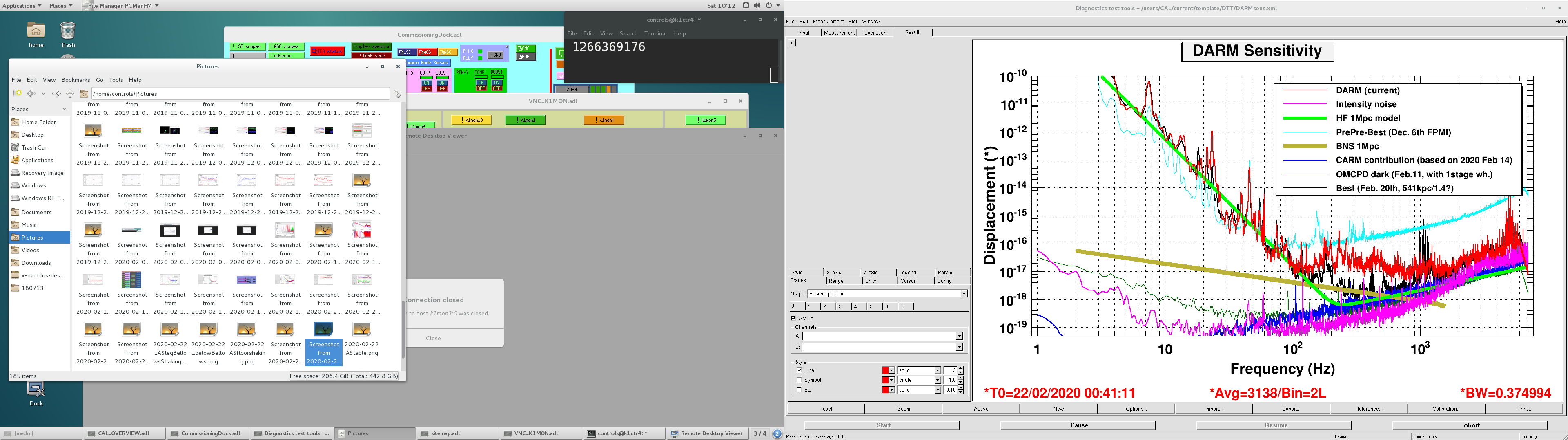
Fig. 2: Point below the bellows shaked.

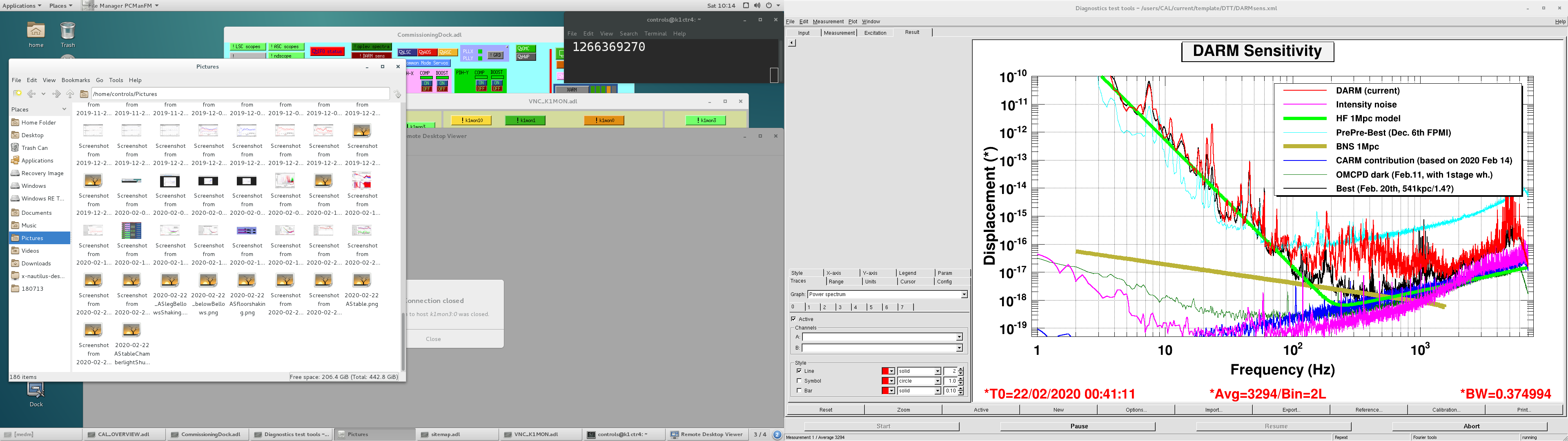
Fig. 3: AS table shaked.

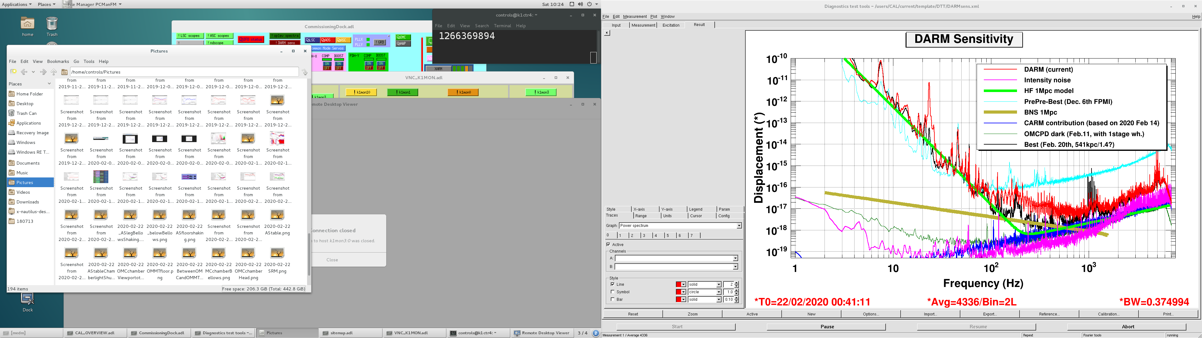
Fig. 4: AS table shaked with the light shutted out at the view port.

Fig. 5: OMC chamber bellows is shaked.

Fig. 6: The floor on the other side of OMC chamber view port is shaked.

Fig. 7: SRM chamber is shaked.

Images attached to this report
Comments to this report:
takaaki.yokozawa - 4:59 Sunday 23 February 2020 (13114) Print this report

I added the working memo by Saito-san,


09:33, 34, 35 view port covering
09:38 vibrating cables and view port
09:41 vibrating chamber
09:43 vibrating bellows >> lock loss
10:03 vibrating bellows/upper: chamber side
10:04 vibrating bellows/lower: floor side and floor( inside groove)
10:05 stopping all FFUs (OMC) 
10:09 vibrating and hammering floor(outside groove)


10:10 vibrating AS table, and also foot
10:12 scattering test btw chamber and AS table
10:12 hammering table (noise floor) and floor (noise peak)


10:14 hammering chamber foot


10:16 hammering floor


10:18 hammering duct btw the chambers
10:19 touching bellows btw the chambers


10:20 hammering chamber lid


10:25 hammering chamber
10:57 hammering outer frame, floor and side hatch
11:00 hammering chamber
11:03 stopping all FFU (SR3-SRM-OMMT-OMC)

takaaki.yokozawa - 6:42 Sunday 23 February 2020 (13116) Print this report

I evaluated "very very preliminary" noise projection from AS table accelerometer to DARM when we injected the vibration to AS table.

250-350Hz has possiblity to limit the noise in DARM sensitivity.

Images attached to this comment
shinji.miyoki - 19:48 Sunday 23 February 2020 (13126) Print this report

Before we asked Kozakai-san for recording, do we remeber that the sensitivity got worse when Uchiyama-kun, Washimi-kun shielded the laser beam from the window to the camera and so on on the ASC table with " some shielding material (maybe a paper ??)"

Actually, saito-sensei made a memo as

09:33, 34, 35 view port covering.


I remember that the sensitivity became quite worse  for the sweet spot frequency range around from 100Hz to 300 Hz when the optical path was shileded and scattered light was generated at this shielding point.

Did washimi-kun put some vibrators on the vacuum tank at the same time ? If you PEM team don't remenber this, please check again if possible.

shinji.miyoki - 20:10 Sunday 23 February 2020 (13127) Print this report

[Aso-kun's comment via gokagra posted by miyoki]

I think Somiya-san did some calculation on the vibration isolation requirement of OMC.
Theoretically, the coupling of the OMC vibration into DARM should be very small.

For example, in the OMC length sensing signal, we can see huge peaks around 90Hz.
From the shape, they look like mechanical vibration modes of OMC.
However, these peaks are totally invisible in the DARM signal.
This is an evidence that the actual length change of OMC does not couple much to the DARM signal.

About the strong vibration coupling from the OMC chamber, I suspect either scattering or beam clipping.

shinji.miyoki - 20:11 Sunday 23 February 2020 (13128) Print this report

[Somiya-kun's comment via gokagra posted by miyoki]


I have two comments. One is that the coupling from the OMC jitter to the DARM signal can be minimized with a proper alignment but the proper alignment can be different from the proper alignment to maximize the DARM signal transmission. See the attached file.
Note that the simulation is without the ITM birefringence.

If the OMC alignment is set to maximize the carrier light at the PD, then it is the minimum point for the OMC jitter coupling.
Anyhow, it is worth trying to modify the OMC alignment to see if the coupling decreases.

The other comment is that the scattering could be coming from the OFI, not the OMC. My calculation said the noise level is lower than the final sensitivity, but the amount of the junk light can be higher than the estimate.

shinji.miyoki - 20:12 Sunday 23 February 2020 (13129) Print this report

[Nakano-kun's comment via gokagra posted by miyoki]

How about trying to tweak OMC alignment?
Possibly,  bad alignment cause larger coupling with angular motion.

takashi.uchiyama - 21:57 Sunday 23 February 2020 (13130) Print this report
09:33, 34, 35 view port covering

During in this period, I looked for the laser beams from the view port by a sensor card.
Initially I took the sensor card relatively closed to the view port.
The sensor card was shined by the laser beam and scattered light at the card could be reflected into the chamber.
It might be the moment the sensitivity got worse.

After then, Yokozawa-Sama asked me taking the card far away from the view port and I did so

Miyoki-SAN’s question: Did washimi-kun put some vibrators on the vacuum tank at the same time ?.
May be not.
Shaking by Washimi-Sama was done after the these activities.
tatsuki.washimi - 22:15 Wednesday 11 March 2020 (13483) Print this report

I analized this data.

Background : 1266369053-1266369077
Injected : 1266368990-1266369014
Main channel : K1:CAL-CS_PROC_C00_STRAIN_DBL_DQ
Monitor channel : K1:PEM-ACC_OMC_TABLE_AS_Z_OUT_DQ


However, in this measurement,

  • This ACC was not on the OMC foot, but on the AS table.
  • injection was not stable (plot) and not enough (plot) ->  So I used 2σ threshold.
  • interferometer will be updated.
Images attached to this comment
Search Help
×

Warning

×