With Lucia and Terrence.
The oplev was diagonalized according to the scheme described in entry 10729.
- I wrote a procedure which anyone who does not know the system in detail may be able to follow.
-
A script (written by Lucia and Terrence) is used in order to
- Identify the exact position of the resonance peaks from amplitude spectral densities ,
- Read the cross-coupling ratios from transfer functions at the resonant frequencies and
- Calculate the new diagonalization matrix.
- I wrote some comments in the script but it likely requires more.
- The final results are given as coupling ratios with appropriate units in terms of µrad and µm. For example, the ratio for L to P coupling should be in units of µrad/µm.
- Note that in other klog entries these ratios are written without the appropriate units and multiplied by a factor of 100 with a percetage sign.
Procedure
- The suspension was set to TWR_DAMPED state manually. At the time of this work Guardian was not working properly. It migh have been fixed by the time of posting.
- Using the marionette the mirror was aligned using actuation offsets. With that version of the oplev diagonalization matrtix the orientation was pitch = -10 µrad and yaw = 12 µrad.
- From Input X directory I copied the file templates to directory /users/VISsvn/TypeApayload/ETMX/Spectra/20190930/ and changed the file names accordingly.
- I opened the file SPE_ETMX_OPLEV_DIAG_check_Y_noiseinj.xml, changed the channel names accordigly and excecuted it. The actuation is white noise applied along marionette in yaw.
-
I exported crossed transfer functions into text files in the SCRIPT subdirectory as follows:
- File name: Y2L_Y2Pratio.txt
- Columns: Frequency, Y to L ratio magnitude, Y to L ratio phase, Y to P ratio magnitude, Y to P ratio phase.
- The channels used for the ratios are the TM_DAMP channels, e.g. K1:VIS-ETMX_TM_DAMP_L_IN1_DQ for longitudinal.
-
I exported the amplitude spectral densities into text files in the SCRIPT subdirectory as follows:
- File name: Yexc_L_P_Yspectra.txt,
- Columns: Frequency, L, P and Y.
- The channels exported are TM_DAMP channels.
- I opened the file SPE_ETMX_OPLEV_DIAG_check_Pnoiseinj.xml, changed the channel names accordingly and excecuted it. The actuation is white noise applied along marionette pitch.
-
I exported crossed transfer functions into text files in the SCRIPT subdirectory as follows:
- File name: P2L_P2Yratio.txt.
- Columns: Frequency, P to L ratio magnitude, P to L ratio phase, P to Y ratio magnitude, P to Y ratio phase.
- As with the other file, the channels used for the ratios are the TM_DAMP channels.
-
I exported the amplitude spectral densities into text files in the SCRIPT subdirectory as follows:
- File name: Pexc_L_P_Yspectra.txt,
- Columns: Frequency, L, P and Y.
- The channels exported are TM_DAMP channels.
- After the residual motion of the mirror was damped its position and orientation was noted. When the IP was at nominal IP-L = 0 µm, oplev L = 25 µm, P = -10 µrad and Y = 8 µrad.
- I moved the IP by 100 um longitudinally per lP LVDT. The actuation was achieved by changing the IP position setpoint from the medm screen: VIS_ALL → ETMX TOWER → IP SETPOINT → L OFFSET.
- I noted the new position and orientation of the mirror: When the IP was at IP-L = 100 µm, oplev L = 25 µm, P = -10 µrad and Y = 8 µrad.
- I calculated the oplev cross-coupling ratios ΔY/ΔL =19/123 µrad/µm and ΔP/ΔL=0 µrad/µm from the oplev readout.
- I opened the Matlab script ETMX_TM_OPLEV_DIAG.m and scrolled down to the comment line "% Hello user, please write the L2P and L2Y cross-coupling ratios below this line!".
-
I modified the values of two parameters:
- l2p = 0 (which is ΔP/ΔLabove in units of µrad/µm).
- l2y = 19/33 (which ΔY/ΔL is above in units of µrad/µm).
-
In the medm screen there is already a diagonalization matrix whose value has to be included in the calculation.
- Its location is VIS_ALL → ETMX CRY-P →SENSMAT in TM OPLEV section. There are other marices called SENSMAT but the one I used was the one in the TM oplev section.
- I modified the Or matrix as follows: Or=[0 -0.1511 0 1; 1 0 0 0; 0 1 0 -0.0720] ;
-
Finally, I excecuted the Matlab script and got a new diagonalization matrix called "new".

- In TWR_DAMPED the all control loops of the payload were off, including the TM oplev control loop over the marionette. Therefore, it was safe to change the value of the SENSMAT matrix.
-
After changing the matrix the values, the readout values of pitch and yaw changed but not the real orientation of the optic, which remains in the aligned orientation. I recorded the new values in the medm screen:
- SITEMAP →Commissioning→Commissioning TOP→Alignment Tools→All oplevs→! record oplev 2→ETMX.
- Pitch: -10 µrad.
- Yaw: 8 µrad.
-
I measured again the ASDs after the diagonalization. I expected I used actuation in order to estimate the new cross-coupling ratios. Those measurements are in files:
- SPE_ETMX_OPLEV_DIAG_check_Y_noiseinj_afterdiag.xml
- SPE_ETMX_OPLEV_DIAG_check_Pnoiseinj_afterdiag.xml
- I should have calculated the new cross-coupling ratios L2P and L2Y using the IP (as in steps 10 to 13 above) but I forgot. I will do it when they are not using the suspension.
- I removed the DC offsets in MN OPLEV DCCTRL that kept the mirror aligned.
- The suspension was set to ALIGNED state. Guardian was not fully functional for the payload at the time of this work and Lucia turned the appropriate filters by hand. Additionally, she and Fujii-kun fixed a different problem related with the selection of filters by Guardian (entry 10778).
Coupling ratios before and after diagonalization
| Cross-coupling name | Frequency (Hz) | Before diagonalization ( × 1e-2) | After diagonalization ( × 1e-2) |
| L2P | DC | 0 µrad/µm | missing value µrad/µm |
| L2Y | DC | 15.44 µrad/µm | missing value µrad/µm |
| P2L | 7.523 | 2.29 µm/µrad | 0.13 µm/µrad |
| P2Y | 7.523 | 0.86 µrad/µrad | 0.77 µrad/µrad |
| Y2L | 0.312 | 0.79 µm/µrad | 0.05 µm/µrad |
| Y2P | 0.312 | 0.20 µrad/µrad | 5.91e-3 µrad/µrad |
Notes:
- When actuating in pitch the coupling ratios were calculated with the peak at 7.523 Hz because it had a better signal to noise ratio than the peak at 0.85-ish Hz in the amplitude spectral density.
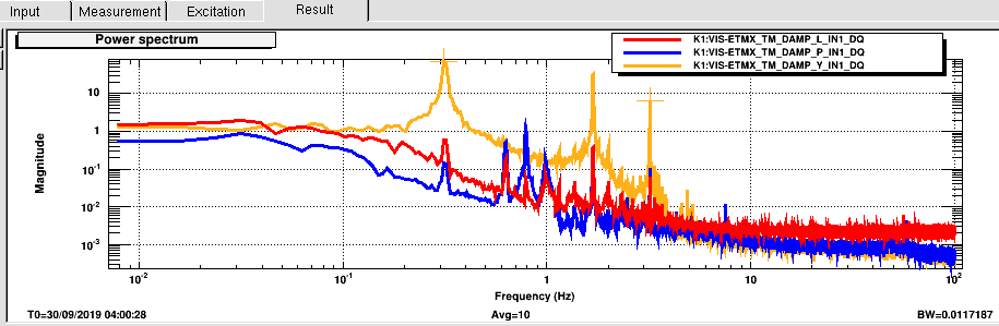
- Question: doesn't this criteria also holds when actuating in yaw? There are resonant peaks wich seem to be better defined above the noise at 1.687 Hz and 3.203 Hz. See the picture from file SPE_ETMX_OPLEV_DIAG_check_Y_noiseinj.xml.
-
We are interested only in resonant peaks which are coherent between the degrees of freedom involved. There may be resonant residual motion which is not is not meaninful for diagonalization. See for instance:
- File: SPE_ETMX_OPLEV_DIAG_check_Pnoiseinj_afterdiag.xml
- Frequency and DoF: 0.312 Hz in yaw.
- Coherence: 0.15
- The large peak appears beause I applied actuation in yaw in a previous measurement and I didn't wait until the motion damped.
