VERY IMPORTANT NOTE: By L2P I mean L displacement observed in P readout and vice versa.
With Ushiba-san, Aso-san, Lucia, Fabian,
In addition to confirm the diagonalization that Nakano-san did in 10708, we finialized a diagonalization scheme for optical levers for Type A suspension which will be used for automatic diagonalization in the future.
Let L', P' and Y' be whatever length, pitch and yaw that are shown in the channels and L, P and Y be the real longitudinal, pitch and yaw displacement. Assuming the each readout is a linear combination of the real displacements, then we can write
L' = A_{LL}*L + A_{PL}*P + A_{YL}*Y
P' = A_{LP}*L + A_{PP}*P + A_{YP)*Y
Y'= A_{LY}*L + A_{PY}*P + A_{YY}*Y
where A_{ij} is the the amount of displacement in i direction as seen in the j' channel, also referred as i2j coupling ratio.
A_{ij} can be obtained by measuring the ratio i/j' at pure j' resonance frequency and A_{ii} is assumed to be 1.
To do measurement, there are two ways. The first way is to inject an impulse actuation to the suspension and then measure the amplitude spectrum while the suspension is free swinging. The second way is to measure the ASD while injecting white noise.
The rationale for the first method is to avoid the addition of coupling from actuation so we can measure pure sensor coupling. However, as is seen in 10595 where Jenne and Lucia did the first free swinging diagonalization, the signal to noise ratio is very low, meaning that we might not be able to reduce the coupling ratio below the noise to signal ratio. And, in the case of 10595, we'll not be able to decouple the signals down 1% coupling.
With the white noise injection approach, the resonances are continuously being excited so we will be able to see peaks much higher than the noise floor. I argue that this approach is better because we get more accurate coupling ratios. One would argue that if there exists imbalance in the actuation, we would confuse sensor coupling with actuation coupling. But, this is not the case because white noise is flat so actuation coupling appears flat while sensor coupling will show as peaks at resonances. Therefore, if we choose to measure coupling ratio at resonances, this method holds true as long as the peaks are much higher than the flat region.
Because the suspension has no pure L modes are always coupled with P, there is no good mode to be selected for measuring A_{LP}. So, I instead proposed to do another measurement involving the translation of the IP. In principle, if we translate the IP horizontally using a DC offset, everything suspended by the top filter should follow and the optic should remain the steady in pitch unless something is terribly wrong with the suspension. Therefore, we can offset the IP and measure A_{LP}=(change in P')/(change in L') (assuming A_{LL} >> A_{PL}, A_{YL}. The same is no so true for yaw because we cannot trust that the IP moves purely in translation but not yaw, so it really depends of the level of diagonalization we get from the IP.
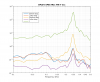
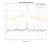
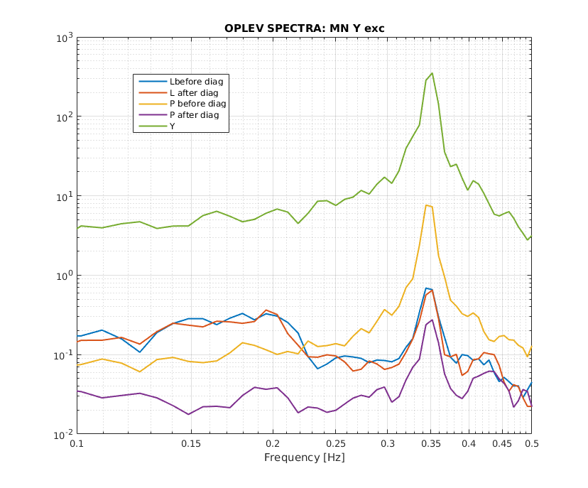
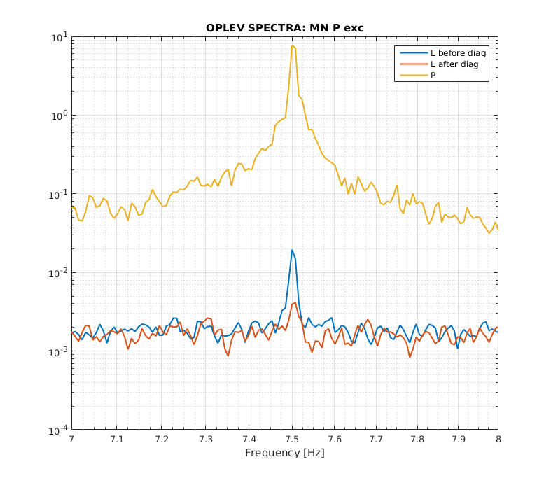
With the diagonalization scheme decided, we tested it with ETMY. We measured L', P' and Y' spectrum while L, P and Y were excited separately and we measured coupling ratios of L2Y (at 0.65 Hz), P2L (0.85 or 7.5 Hz), Y2L (0.35 Hz), Y2P (0.35 Hz) and P2Y (0.85 or 7.5 Hz) and use the phase to decide the sign. In the case of P2Y coupling, the phase is something like 40 degrees so this information is not so useful unless it's close to 0 or ±180. But, the coupling ratio was less than 1% anyway so it doesn't really matter as this is our target. Then, we translate the IP in L by 100 um and measure the change in L' and P'. After that we applied the inverse of the A matrix to the original matrix to obtain a new sensing matrix for the optical lever.
We measured the spectrum again and we immidiately noticed that using the 0.65 Hz pendulum mode for measuring L2Y coupling isn't so effective. Nakano-san's original theory was that there will be some tranverse to yaw coupling because of the wedged surface of the optic and because the transverse pendulum mode is also at around 0.65 Hz. However, we argued that the we should be able to achieve a ''pendulum mode-free" yaw channel because the effect of transverse displacement is just shifting the beamspot of the optical lever at the optic plane in longitudinal direction. This transverse motion coupling is common for both tilt and length sensing QPD so we would be able to cancel it but leaving a transverse coupled length sensing signal. So, we don't really know what is happening at 0.65 Hz as we look at the ~100% L2Y coupling. All we can do is to do the same DC translation in the IP to measure a not-so-optimal L2Y coupling ratio. It turned out the L2Y coupling ratio we measured using this method is exactly the same (well, off by 0.2%.) as what Nakano-san obtained with the interferometer in 10708. So, this confirms that we can do diagonalization without involving the interferometer.
In figure 1, we can see the the coupling ratio Y2P was originally around 1% and we got it down to less than 0.1% after diagonalization. But, we didn't get much reduction in Y2L coupling but it was very small anyway. In the second figure, P2L coupling was 0.25% and we got it down to 0.05% after diagonalization. We cannot tell how well we get for L2P coupling, L2Y coupling just because there is no way to confirm. But, I believe that those are really small unless the interferometer and the suspension are all wrong.