Reports 1-1 of 1 Clear search Modify search
VIS (SR2)
fabian.arellano - 10:52 Friday 13 September 2019 (10510) Print this report
LVDT correction with seismometer.

The filter bank where the integrator to convert the seismometer readout from velocity to displacement seems to be missing. The automatically generated medm screen points to file K1ALSFIB.txt with module X_FIBER_TEMP_SERVO. This  has to be fixed, nevertheless, I still measured transfer function from ground seismometer to IP LVDT with the suspension in FLOAT state. The integrator should be applied to the measured data.

Directory:

/kagra/Dropbox/Subsystems/VIS/TypeBData/SR2/TF/Measurements/20190913/

File:

TF_seis2IPLVDT_20190913.xml

Images attached to this report
Comments to this report:
fabian.arellano - 14:16 Thursday 03 October 2019 (10823) Print this report

In case you don't see the plots attached please click here: 10823.

Summary in the context of the commented entry

  • The reported problem with the filter bank was solved.
  • I compared the transfer functions from the seismometer on the ground to the IP-LVDT.

Transfer function: measurement and prediction

The plot attached shows the comparison between a measured transfer function and the model prediction. A second plot shows the coherence of the measurement.

  • DoF: from seismometer-on-ground-Y-arm to IP-L
  • The coherence is larger than 0.5 between 100 mHz and 515 mHz and from 515 mHz to 615 mHz it's intermittently larger than 0.5.
  • There's a pendulum mode resonance at 405 mHz properly predicted by the model.

The Matlab model used does't properly take into account structural damping and a suitable improvisation or fix has not been implemented. Therefore it's not surprising that the predicted amplitude of the large peak below 100 mHz does not coincide wih the measurement. In any case, below 100 mHz the coherence is low. Nevertheless, the general features of the model do coincide with the measurement, including the shape of the transer function when going from the IP resonance below 100 mHz to the pendulum mode resonance at 405 mHz.

Images attached to this comment
fabian.arellano - 16:24 Thursday 03 October 2019 (10824) Print this report

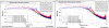
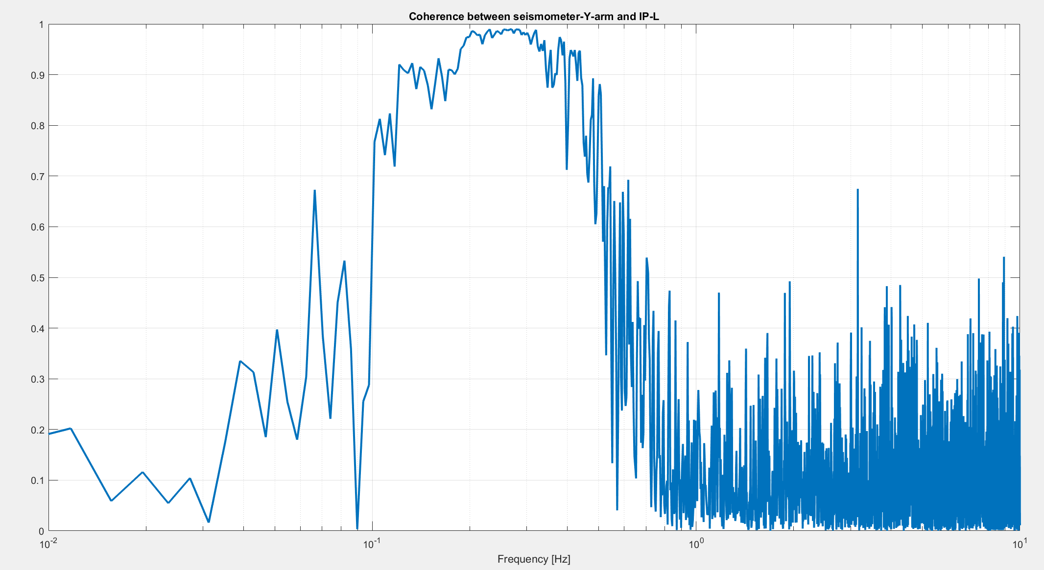
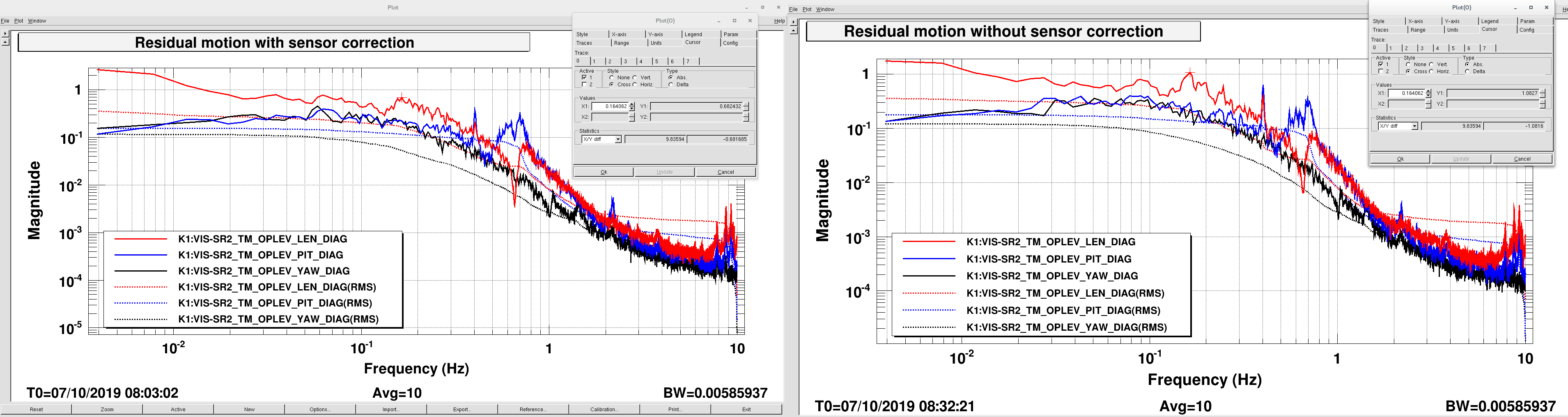
Having compared the measured transfer function with the model prediction I went ahead and implemented the sensor correction for IP longitudinal. I just added filters to the filter bank but I haven't test them yet because they are using the suspension for the main interferometer. The implementation for IP transverse will follow.

About the seismometer

  • Its signals are proportional to the velocity. Therefore, it requires an integrator in order to estimate the displacement. The filter name is "vel2disp".
  • The signals have an offset which is not compatible with the integrator.
  • The DC offset was removed with a 4th order Butterworth high-pass filter with a cutoff frequency of 0.5 mHz. The filter is called "DC_removal".
  • The seismometers we use are good above 40 mHz. We know this because Miyo-kun placed two seismometers of the same kind next to each other and there was no coherence below 40 mHz.
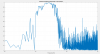
  • The components of the signal below 40 mHz are removed with a 2nd order elliptic high-pass filter with a cutoff frequency of 10 mHz, a 10 dB passband ripple and attenuation of 100 dB. The filter is caled "TF_GND2IP" (see below).
  • This implementation follows the X End suspension implementation.

About sensor correction

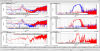
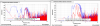
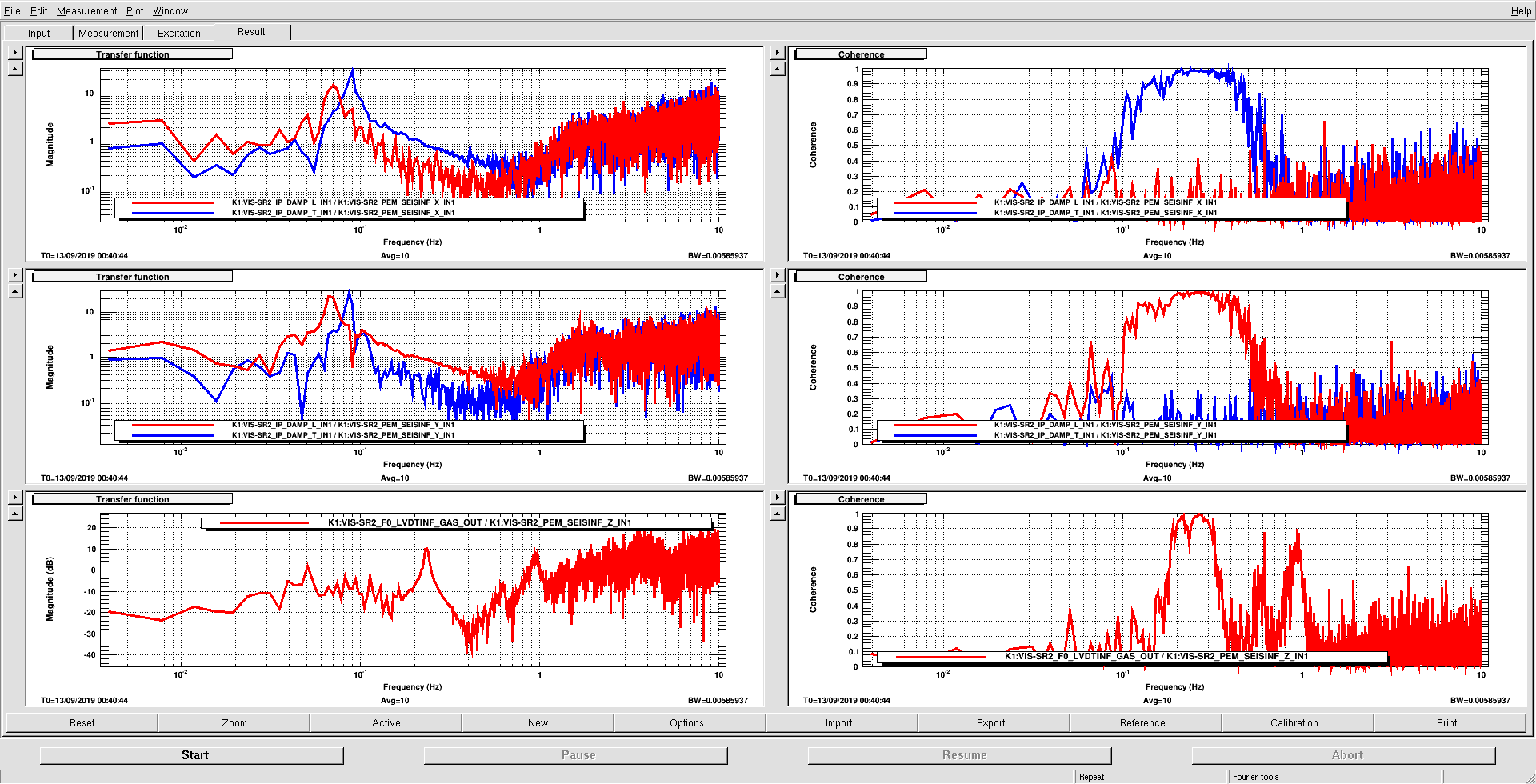
The amplitude of the ground motion is estimated by multiplying the seismometer signal (filtered as above) by the transfer function from the seismometer signal (along the Y arm) to the IP longitudinal. This operation is suitable only in those frequency bands in which the transfer function theoretically equals one. This happens in the region above the resonant frequencies, where the IP table does not move following the ground yielding the LVDT sensitive to the motion of the ground only. Although the transfer function equals to one in theory, in practice it does not because possible differences in the calibrations of the IP LVDT and seismometer, for example.

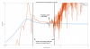
In the case of SR2 IP-L there is a resonant frequency at 405 mHz and the coherence is larger than 0.5 continously from 0.1 Hz to 0.515 Hz. From 0.515 Hz to 0.615 Hz the coherence is larger then 0.5 discontinously. Therefore, in order to calculate a value for the transfer function above the highest resonant frequency I consider only those data point between 0.515 Hz and 0.615 Hz whose coherence was larger than 0.5. The final estimate was the average of those values, which is 1.3530.

This value was implemented by adjusting the gain of the filter called "TF_GND2IP".

I will test performance whenever the suspension is available.

takaaki.yokozawa - 6:27 Friday 04 October 2019 (10831) Print this report

Why you used the BS seismometer for the censor correction?

In my opinion, IXV seismometer is much better than BS seismometer.

fabian.arellano - 11:30 Friday 04 October 2019 (10835) Print this report
  • I asked Miyo-kun about the differences between the seismometers. The one upstairs seems to be more sensitive, but I still don't have any quantitative information.
  • According to his experience there's coherence between the two of them below 400 mHz. It might be a good idea to use it but further consideretion may be necessary.
  • The real-time model providing the readout of the seismometer upstairs is not connected to the Dolphin network but provides information to other models using a reflective memory network. Connection would be possible via LSC or ASC models.
fabian.arellano - 11:46 Friday 04 October 2019 (10836) Print this report

Today sensor correction was implemented for IP-T using the seismometer signal along the X arm. The process is completely analogous to the one described for IP-L.

Notes:

  • The value of the transfer function amplitude calculated was 1.4248.
  • I will test the implementation when the suspension become available.
  • Comparison of the measured transfer function and the predicted one by the model will follow.
fabian.arellano - 10:52 Tuesday 08 October 2019 (10877) Print this report

In case you don't see the pictures attached please click this link: 10877.

Yesterday I checked how well the sensor correction  works.

At the first attempt of measuring the residual motion of the mirror with the corrected sensor I realized that despite the amplitude decreased in the micro-seimic region, below 40 mHz the amplidude increased (as shown in the coherence plot below). Likely this is due to noise in the seismometer. In order to minimize this effect I put a notch at 14 mHz where there's a large bump in the high-pass filter which has the transfer function information. The filters are TF_GNDY2IPL and notch14mHz in filter bank SR2_PEM_SEISINF_X. A similar arrangement was done for the filters along IP-L.

Results

  • Above 100 mHz there's a reduction of the residual motion of the mirror in TM-L. See the first picture. The highest value reduces from 1.08 um/rtHz to 0.68 um/rtHz, which is a 40% reduction.
  • As pointed out above at lower frequencies (below 40 mHz) there's an increase of the residual motion, yielding an integrated RMS similar in both cases: about 0.35 um, which is below the requirement. See the second plot which is the coherence. Such an incresse is likely due to noise in the seismometer.

Files

Directory:

/kagra/Dropbox/Subsystems/VIS/TypeBData/SR2/TF/Measurements/20191007/

File names:

TF_seis2IPLVDT_20191007_no_correction.xml

TF_seis2IPLVDT_20191007_corrected.xml

Images attached to this comment
Search Help
×

Warning

×