[Takahashi, Ikeda]
We took pictures of the space between the SUS blocks with the fiber scope in the OMM chamber. We could see gaps around all the bellows that we could access. We could not access the 2-1, 2-3, and 3-3 bellows.
[Takahashi, Ikeda]
We took pictures of the space between the SUS blocks with the fiber scope in the OMM chamber. We could see gaps around all the bellows that we could access. We could not access the 2-1, 2-3, and 3-3 bellows.
To align GRX and find the good alignment of PR3, we first opened GVs between IX/EX and X arm.
Then, I tweeked PR3 alignment to maximize the GRX PD output, which is aligned just before the vacuum evacuation (klog29131).
After finding the good alignment, we checked the single GRX beam position on ITMX.
Figure 1 and 2 show the Tcam photos with GRX before the earthquke and now.
Though current beam seems slightly shifted from the beam before the earthquake, the amount of shift is not so large and maybe acceptable.
So, we didn't move the POMs yesterday.
After confirming these things, works in the Akutsu-san's reports followed.
[Shimasue, Michimura]
We are preparing a setup for BS transmission and reflectivity measurements around IMC REFL area.
Background:
BS is designed and measured to have 50:50 transmission and reflectivity for s-polarization (Ts=49.96%, JGW-T1503347).
But the BS transmission and reflectivity for p-polarization are unknown (Designed to have Tp=20% or so, AR for p-pol a few %, JGW-T1503347).
To understand what is going on in the IFO for p-pol, we are planning to measure them with an another laser source during this vent.
What we did:
- Assembled a tripod setup with a bread board to install laser source (Attachment #1)
- Assembled a laser injection bench on the bread board (Attachment #2, now resting on IMC REFL table)
- Assembled a tripod setup with a bar to hold a power meter to measure the incident power to the BS and BS reflected/transmistted powerr (Attachment #3)
- We are planning to stick this power meter to ICF203 flanges between BS and ITMX or ITMY (Attachment #4 and #5)
Please see the original report in 2019 (klog 9555).
Ushiba, Aso, R. Takahashi, Shimasue, Ikeda, Hirata, Akutsu; Ref: 16954.
Our objective is to finalize stuffs in IFI, IMM, and PRM chambers, which will be closed in the nex week. The finalization include main beam alignment and alignment relevant ghost beams to beam dumps. Today GRX path was confirmed. Alignmenf of the input IR beam axis to POP_FORWARD through PR2 and PRM is still on the way (we are at proceder #5 shown below).
Refer to Fig. 1.
After FC works (29254), PRM, PR2, PR3, and their BBs were released as planned. For PR3 release, as unfortunately as usual, PR3 was largely tilted and the oplev lost. The alignment was tentatively adjusted with picomotors. Fortutenately PR3 oplev came back, but one of the PR3 OSEMs would be about saturated. Because PR3 Guradian was able to reach ALIGNED, today we accepted this situation at this point. Later we need to adjust PR3 suspension manually.
Opening GRX shutter, and sweeping PR3, GRX transmission was immediately found at TMSX. The would mean that letting PR2 BB releasing/sitting might not so affect POP-POM alignment. This is good news. Also, the GRX spot at ITMX seemed almost the same as the one taken some days ago when the interferometer was nice alignment (the detail of this point will be separately reported by Ushiba-kun?)
Putting a PR2 HR target, we checked GRX spot on this target, and it was not so bad (mostly centerd but slightly shifted), so we left it as was. See Figs. 2 and 3. Then detaching the PR2 HR target, and putting a PR3 HR target, we also checked GRX spot on this target. As written in the above planned procedure, this was just for confirmation; we could not do anything on this spot (Figs. 4 and 5). By the way, when you would insert the target, the suspension should not be at ALIGNED state, as oplev and/or OSEMs might be affected by your beam cut or light illumination. If you are very much careful, you may be able to live with ALIGNED state, though.
Then we started iteration of the IR beam from IMC. As mentioned above, to IO Guardian, we called PROVIDING_STABLE_LIGHT, which means that the input beam axis is fixed to the sub-local area around IMC, and IMMT1T QPD was used as one of references. One should not cut the beam to IMMT1T to keep this alignment control. The iteration is: (1) check PR2 HR target and IR spot on it, and adjust the IR spot on it with IMMT2, (2) check PRM AR target and IR spot on it, and adjust the IR spot on it with IMMT1. (3) Repeat from (1) until the situation converges. But, for some reason, repeating several times, the situation was not so converged. Even more, before converging, for IMMT1 and IMMT2, the oplev range and/or coil actuator range both reached limits. We may start with taking care of these tomorrow morning.
To align GRX and find the good alignment of PR3, we first opened GVs between IX/EX and X arm.
Then, I tweeked PR3 alignment to maximize the GRX PD output, which is aligned just before the vacuum evacuation (klog29131).
After finding the good alignment, we checked the single GRX beam position on ITMX.
Figure 1 and 2 show the Tcam photos with GRX before the earthquke and now.
Though current beam seems slightly shifted from the beam before the earthquake, the amount of shift is not so large and maybe acceptable.
So, we didn't move the POMs yesterday.
After confirming these things, works in the Akutsu-san's reports followed.
[Kimura, M. Takahashi and Sawada (Hokuto)]
On the morning of Apr. 17, one failed helium compressor (Xfs) at IXC was replaced due to a suspected IXC failure.
(klog28051)
This compressor is the compressor for IXC's duct shield cooling cryo-cooler.
The removed compressor will be repaired.
[Kimura and Ueda (SKS) ]
On the morning of April 17, a vacuum leak test was performed on the closed flanges around IXC and IXA.
The vacuum leak test results showed a large leak of more than 3.9 x10^-9 Pam^3/s at the +Y side flange of the cross tube.
Since this leak affects the cooling of the mirror, it is necessary to repair the leak by pressurizing the vacuum chamber to atmospheric pressure.
High purity air with a low dew point was arranged for pressurization.
[Araki (KEK) and M. Takase]
We finished surveying the V-type Chamber (IYV) after pumping down on Apr. 17.
Could you please tell us when is the last measurement? before the Noto earthquake?
If so many positions are contacted, I am afraid that the optical table rotation angle may change because of the friction forces at these contacting points.
I checked the condition of the stack partially with an inspection mirror in the IFI and IMM chamber. I could see gaps between the SUS blocks much enough to prevent touching.
[Takahashi, Ikeda]
We confirmed the height of the breadboard (BB) in the OMC chamber. We measured the distance between the floor level of the OMC chamber and the top of BB with the laser leveler. The BB top was (135.5-80=55.5mm) higher than the 1000mm point from the floor. This height (1055.5mm) was consistent with the last confirmation (1058-3=1055mm).
[Takahashi, Ikeda]
We took pictures of all the space between the SUS blocks with the fiber scope in the OMC chamber. The conditions are summarized in the table.
O: Small gap, X: No gap, Δ: Touching or very close
| Bellows | 1st | 2nd | 3rd |
| 1-1 | O | X | X |
| 1-2 | O | O | Δ |
| 1-3 | O | X | Δ |
| 2-1 | O | X | X |
| 2-2 | Δ | O | Δ |
| 2-3 | O | O | Δ |
| 3-1 | Δ | O | X |
| 3-2 | Δ | X | X |
| 3-3 | X | - | - |
I prepared an ultra-pure water generation system in the clean booth in front of the draft-chamber booth.
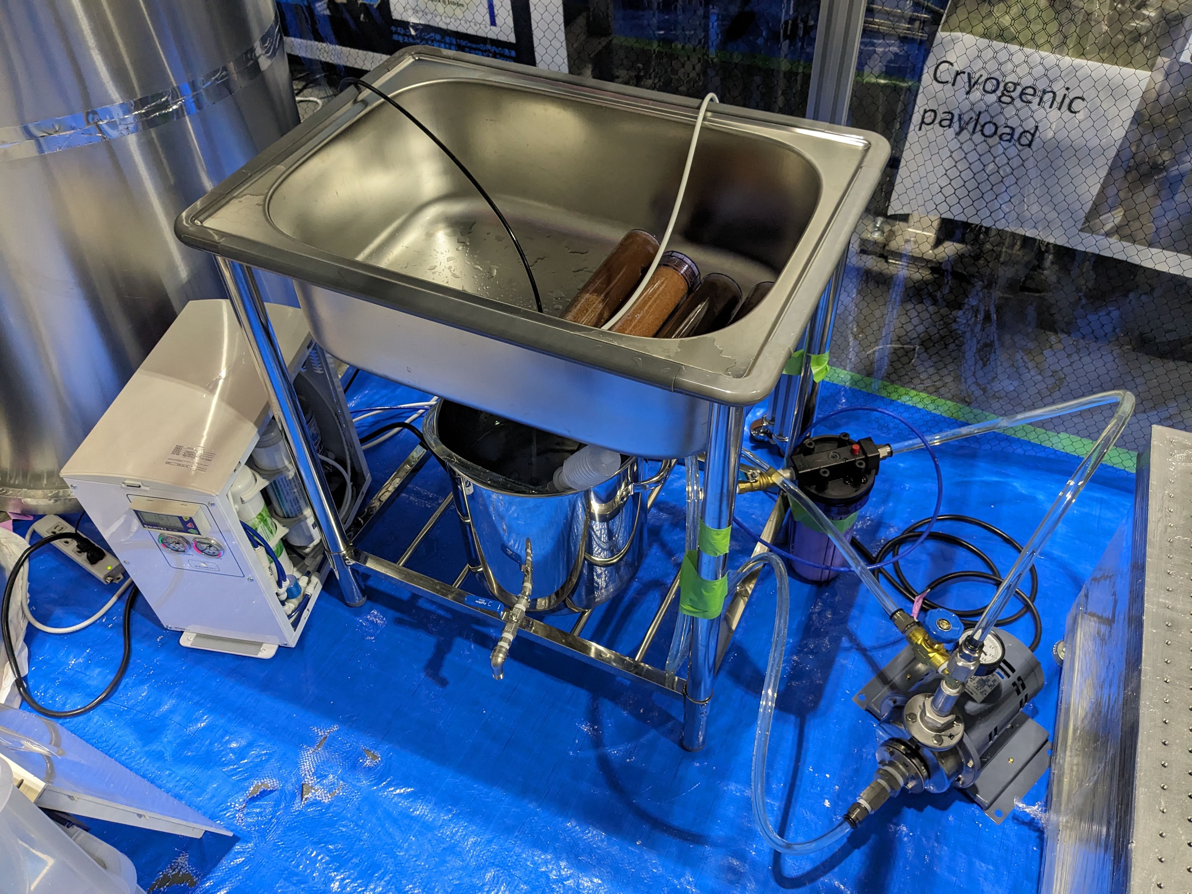
The water circulation system works fine.
However, the ultra-pure water generator (the white machine on the left of the sink) did not work so well.
First of all, the pressure gauge for the RO filter (Reverse Osmosis Membrane Filter) is broken. So we cannot confirm if a proper pressure is applied to the RO filter or not.
Secondly, the purelity of the filtered water is not good. The specific resistance of only 2M [Ohm*cm] was achieved, while it should be above 15M [Ohm*cm] to be qualify as ultra-pure water.
I changed all the filters in the machine. Still the specific resistance was around 2M [Ohm*cm].
I think we should buy a new ultra-pure water generator.
In our previous study, it was not so precise but, the oplev signal and the on-table ACC signal were smaller when I tapped the lower part of the stacks.
Takahashi-san, Ikeda
Continued from K-Log#29182
We have investigated the ETMX F0 YAW stepper motor not working.
We connected a single motor to the end of a DSUB cable and checked that the motor driver was working properly.
Procedure.
1. we disconnected the root of the conversion cable at the end of the feed-through flange and connected the motor we brought in to the motor driver, Fig-1.
2. drive the F0Y stepper motor from the MEDM.
Check that the motor rotates in accordance with the drive volume.
Result.
The motor rotated as expected.
From the above, it can be assumed that the motor driver is normal and the installed motor is driven.
[Hirata, Aso-san]
This morning, we pilled off FC. Still we could see some residues of FC.
After that, we released suspention and lower bread board. And recovered suspention.
I think we should also check the stacks for OMMT, IMMT1 and IMMT2 by the scope. IMC was already closed.
Or do you (or the PEM team) have any data for their isolation function?
This might be one of the main issues we can take care before O4b. A rought list of the sub tasks would include
Well, generally speaking, "not-reviewed installation" is mere putting stuffs but does not mean "installation completion".
[Kimura, M. Takahashi and Sawada (Hokuto)]
On the afrenoon of Apr. 16, one failed helium compressor (P-55) at EXC was replaced.
(k-log 28324)
This compressor is the compressor for EXC's radiation shield cooling cryo-cooler.
The new connecting piping and filter need will be connected.
The removed compressor will be repaired.
[Araki (KEK) and M. Takase]
We finished surveying the V-type Chambers (IXV and EXV) after pumping down.
[kimura]
The parallel threaded seal joint with O-ring, which was the cause of air leakage in the valve drive of the GVetmx, was replaced with a regular tapered threaded seal joint.
After the replacement, a leakage test was conducted, and it was confirmed that there was no leakage.
Replacement with tapered thread seal joints is required for all KAGRA φ1000 gate valves, φ800 gate valves, and pendulum valves.
The following three gate valves are awaiting replacement.
1. GVitmx
2. GVitmy
3. GVetmy
[Kimura and Ueda (SKS) ]
On the aftenoon of April 16, we performed a vacuum leak test on the retightening flanges around EXV, EXC and EXA.
The results of the vacuum leak test confirmed that there were no leakage of more than 1x10^-11 Pam^3/s at the flanges were retightened this time.


.png)
.png)


.png)
.png)