[Ushiba, Tamaki]
Abstract
We researched why V1 sensor for ITMX MN didn't work correctly (klog 17699).
As a result, the loose screw may have affected adversely, so we drove it in. There might be other causes, so we will check the transfer function.
Detailed
As we reported last week (klog 17699), there were strange points in transfer function of MNV1 and MNH3 (DC gains of ITMX H3 and V1 are slightly smaller than those of ETMX's.).
So, we went to IX and investigated the reason of this.
First, we removed the cable which is connected to V1, then the signal of H3 reacted.
Next, we removed the cable which is connected to H3, then the signal of V1 reacted.
These reactions is the expression of the coupling between V1 and H3.
Then, we connected except for 3-8 pin (which is connected to LED), and there was no change.
However, when we connected 3-8 pin, we could see the same signal behavior as we removed the cable which of V1/H3.
This means the LED light may have created mischief so we decided to check it.
Before LED check, we replaced the cable which connected the satelite box and cross cable, but the signal had no change.
Moreover, we connected V1 cable to V2 port. Then, H3 signal didn't reacted, but we could confirm the responce of H2.
According to this reaction (cable sqapping solved problems), there are some defects in the vacuum chamber.
At this time, we thought LED light for V1 (V2) entered the H3 (H2) and made coupling between these sensors because V1 (V2) and H3 (H2) are very close to each other geometrically.
At last, we started the examination in the chamber.
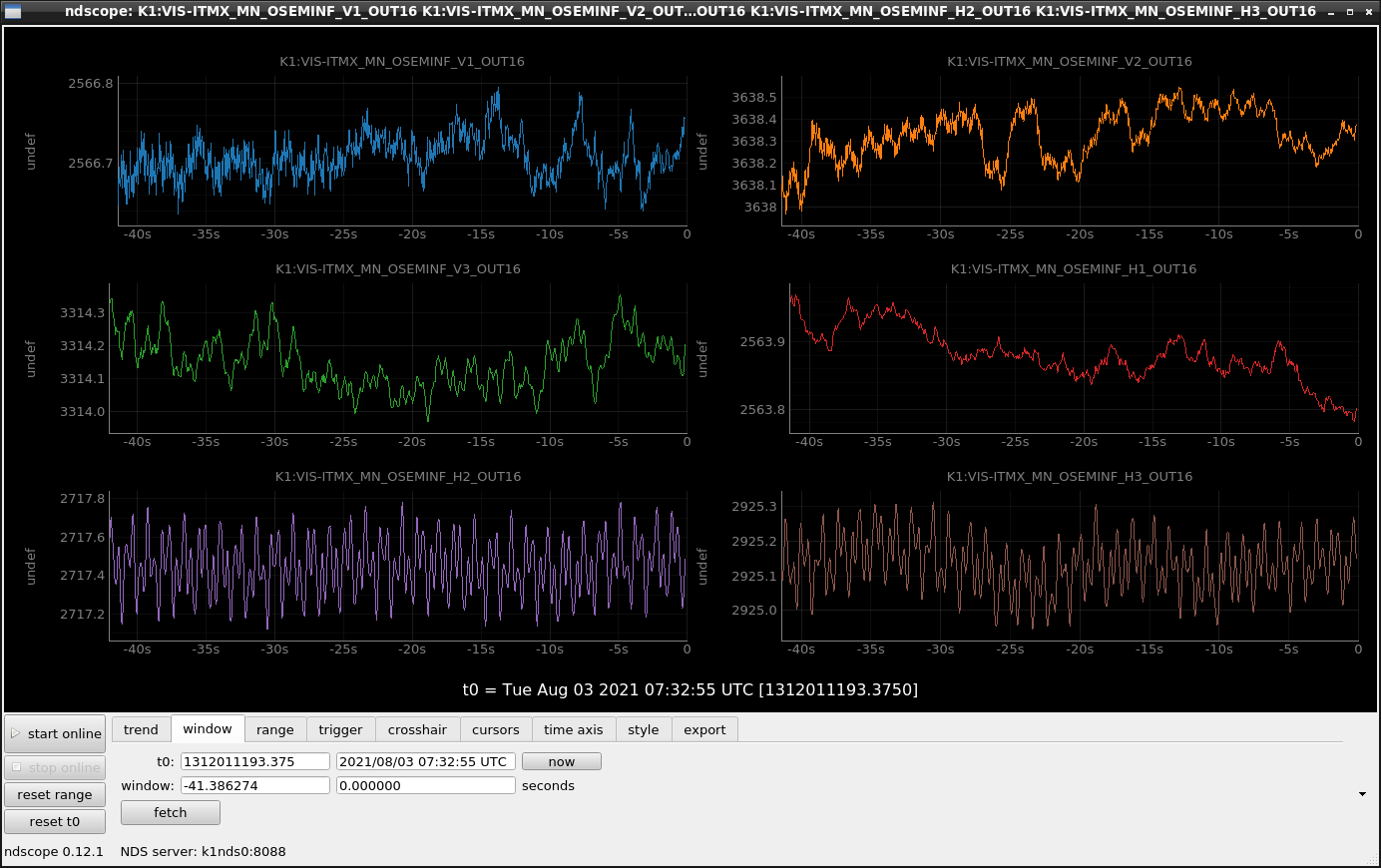
As I menthioned above, we checked the LED light. We blocked the light of V1 and mesured how the signal changed using ndscope but we can't find the signal change.
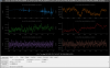
However, we found the signal of V1 has strange points (larger vibration compared with other sensors → please see Fig.1) and the screw around V1 was loose.
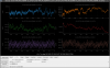
Then, we drove the screw in, and the odd signal disappeared (Fig.2).
From today's activity, we concluded the loose screw had affected to the trouble with V1 but there may be other reason, so we will measure the transfer function again, and check V1 sensor works properly.