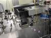
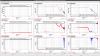
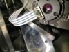
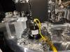
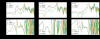
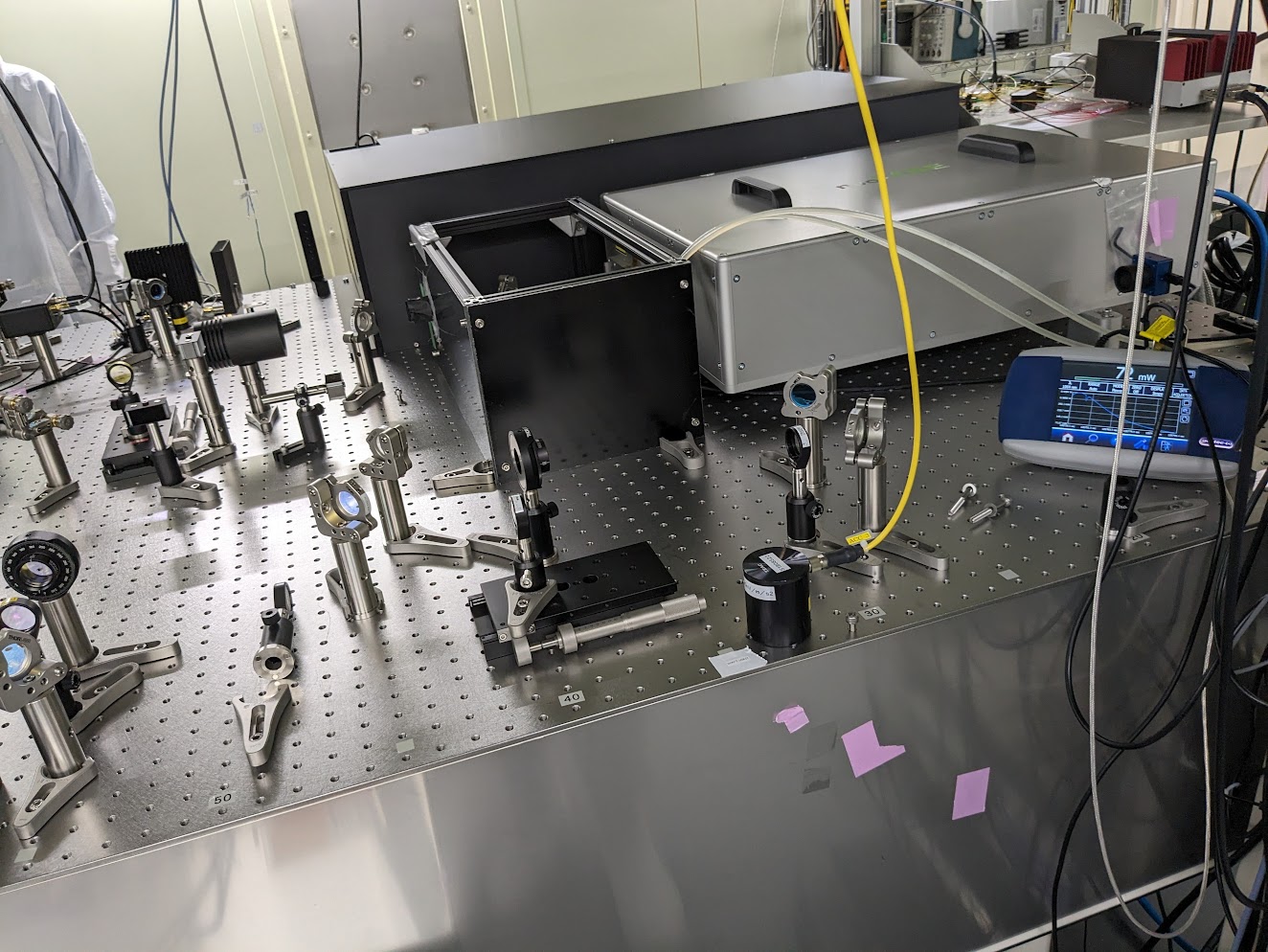
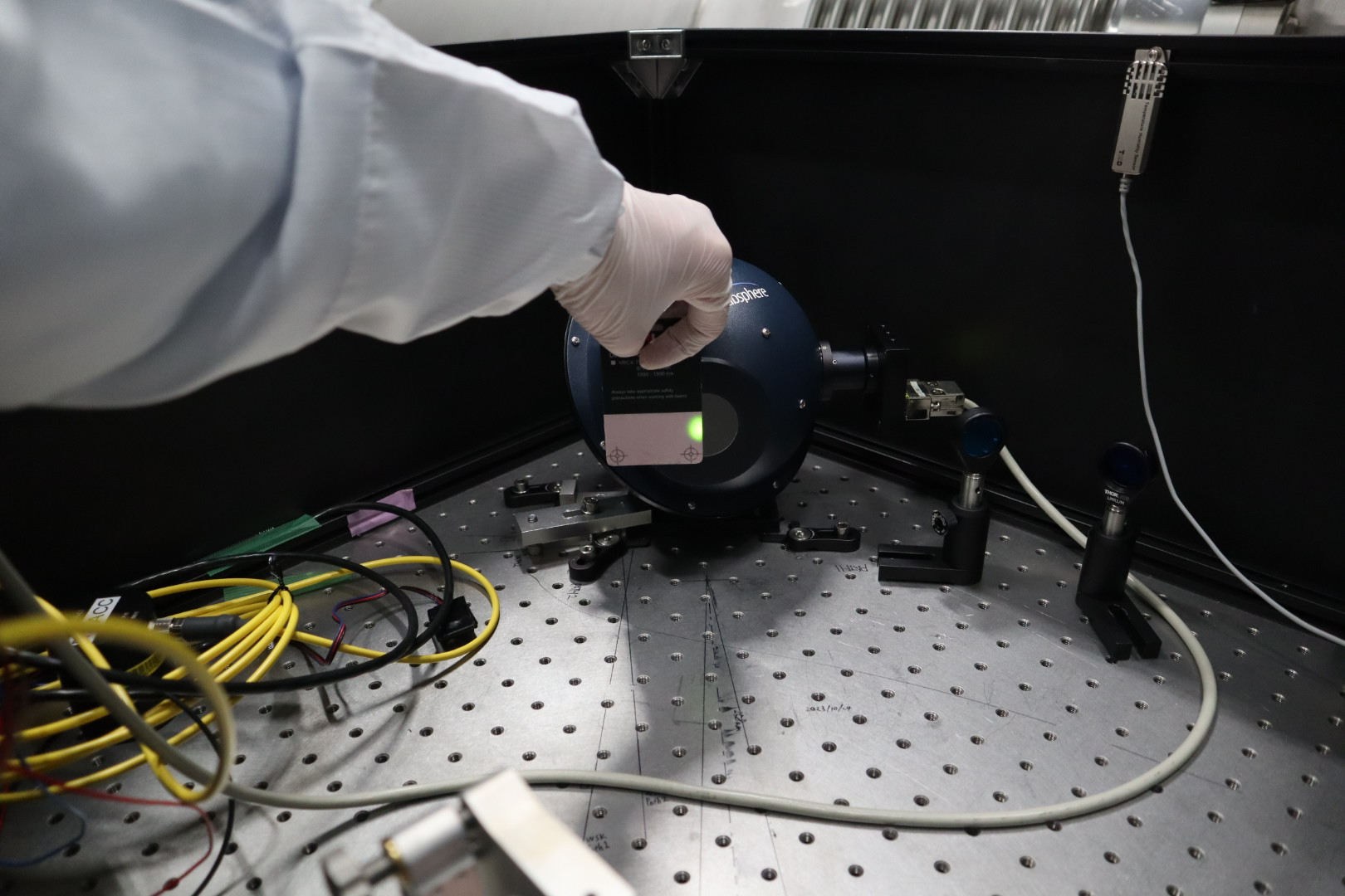
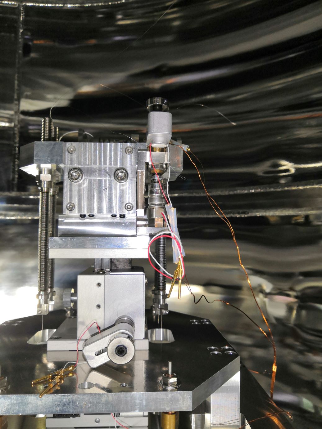
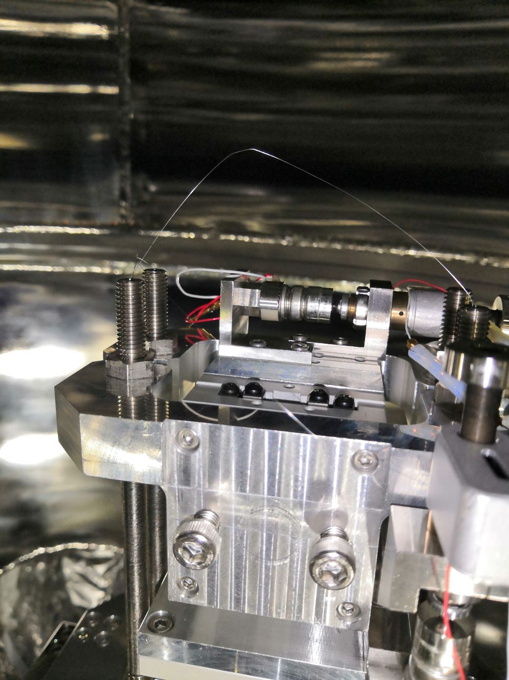
-We aligned the seed laser to the solid amplifier to maximize the output power.
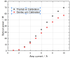
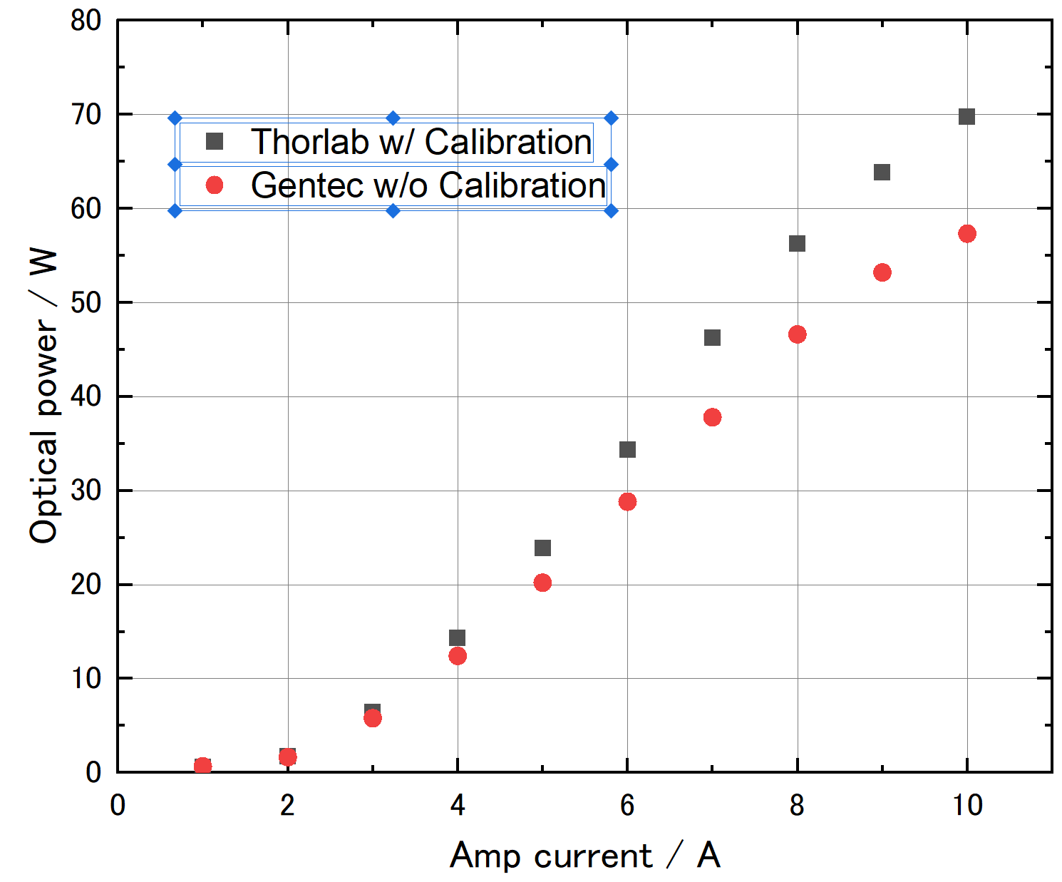
-After the alighnment, we measured the laser light power against the injection current of the optical amplifier using a Thorlab power meter (calibrated) and a Gentec power meter (not calibrated). Attached figure (laser_IP-chara.png) is the characteristics. The laser power measured by Thorlabs is 1.22 times higher than Gentec's.
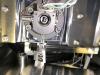
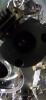
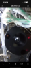
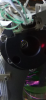
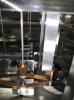
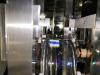
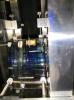
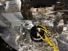
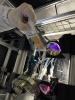
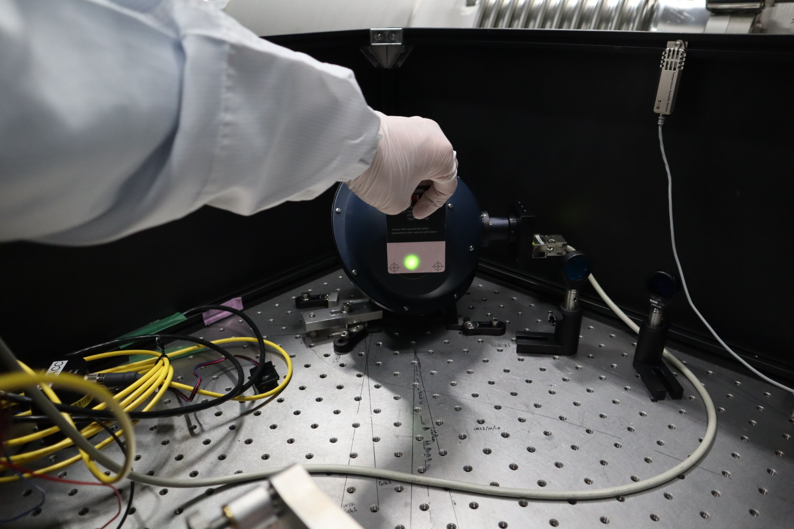
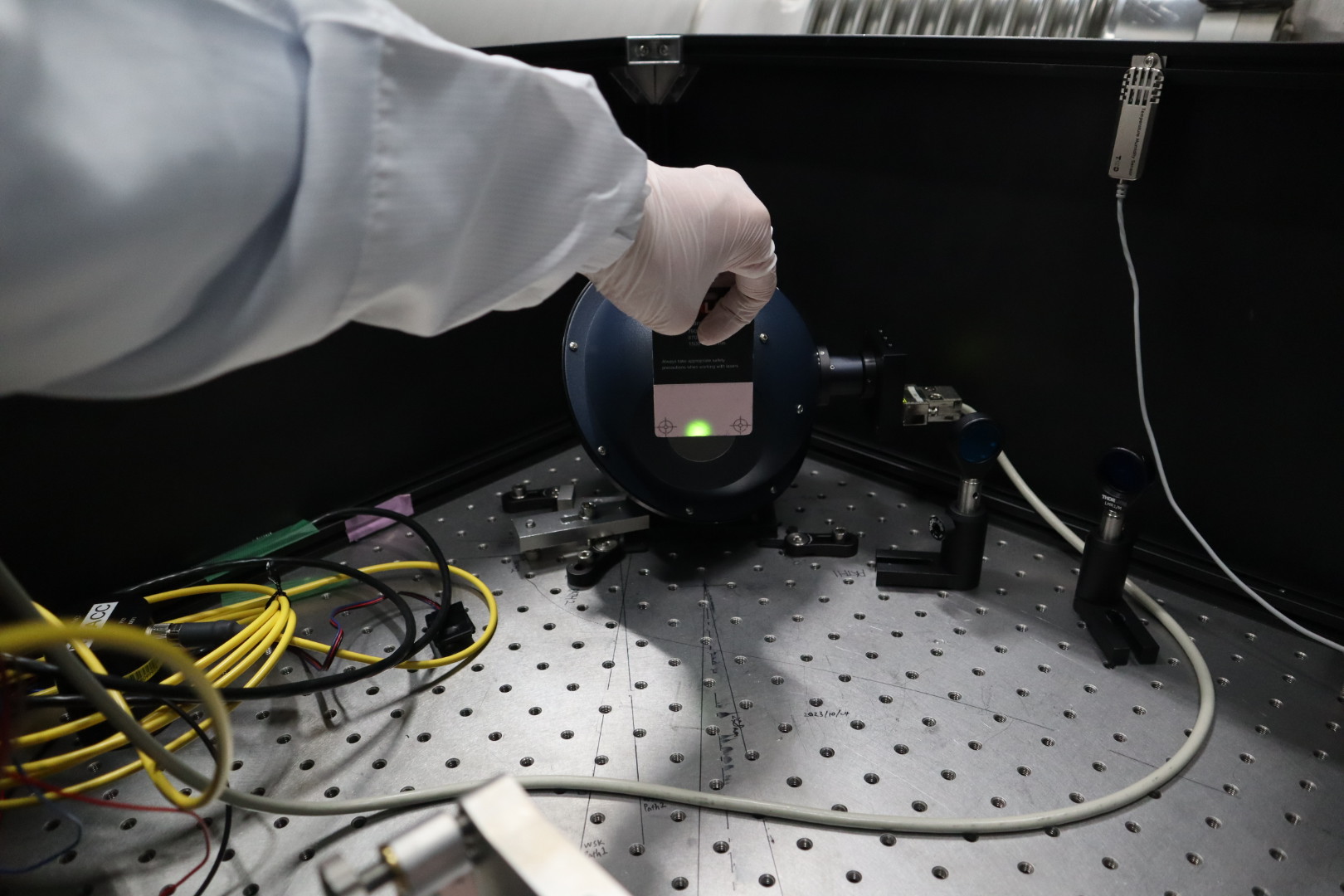
-We set a box (box.jpg) for beam profile measurements later.
With Hido Shingo
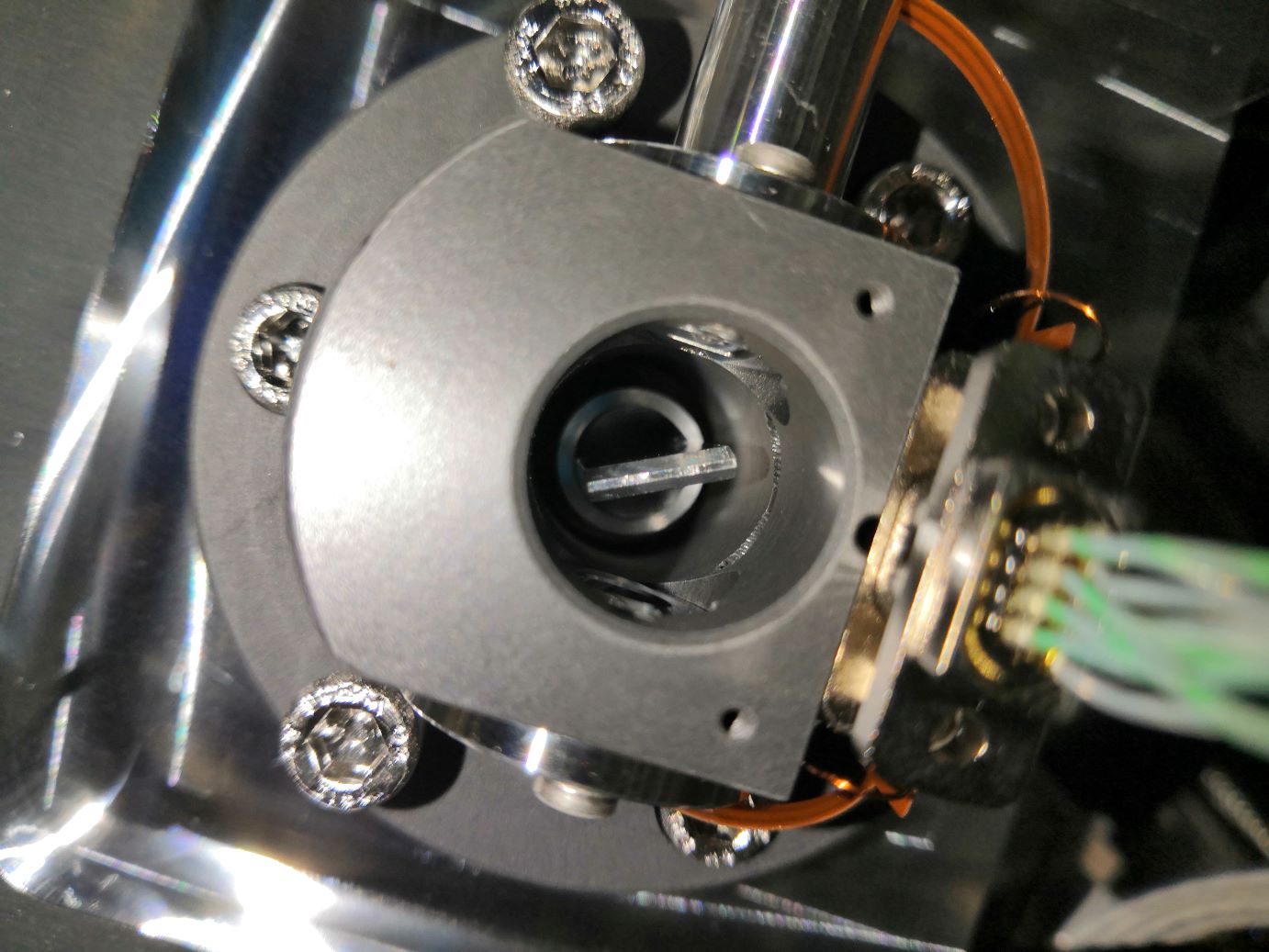
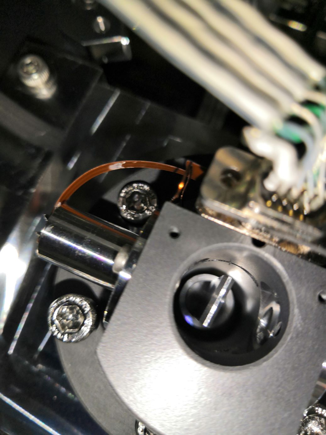
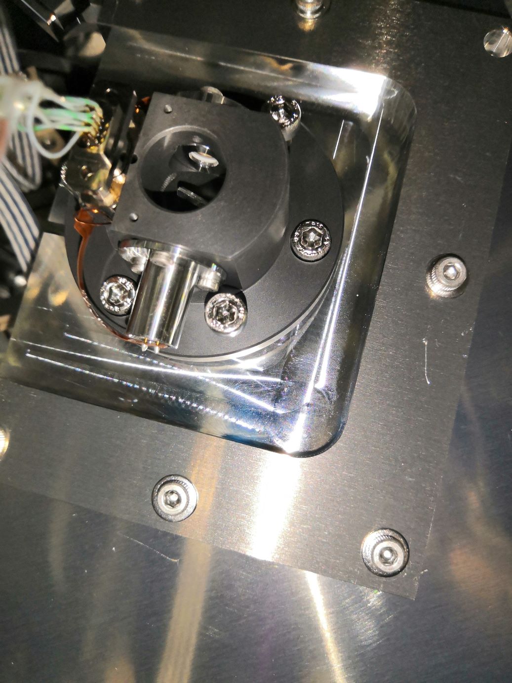
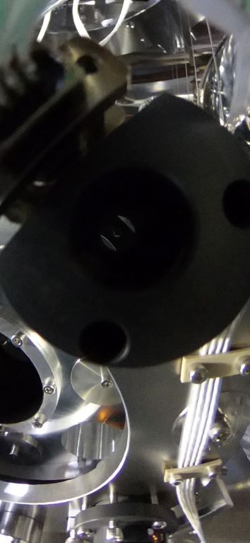
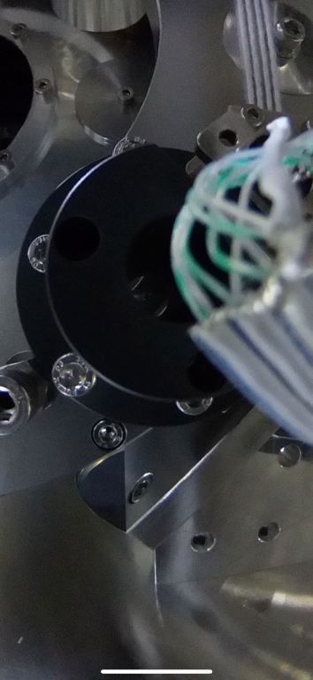
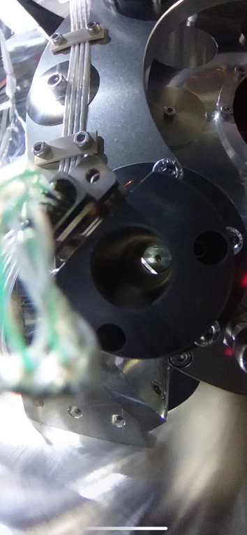
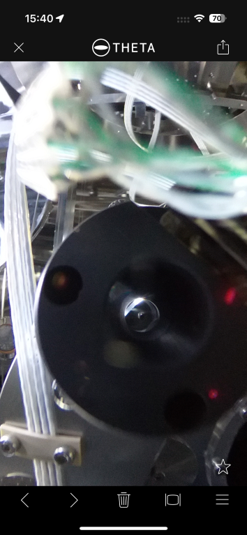
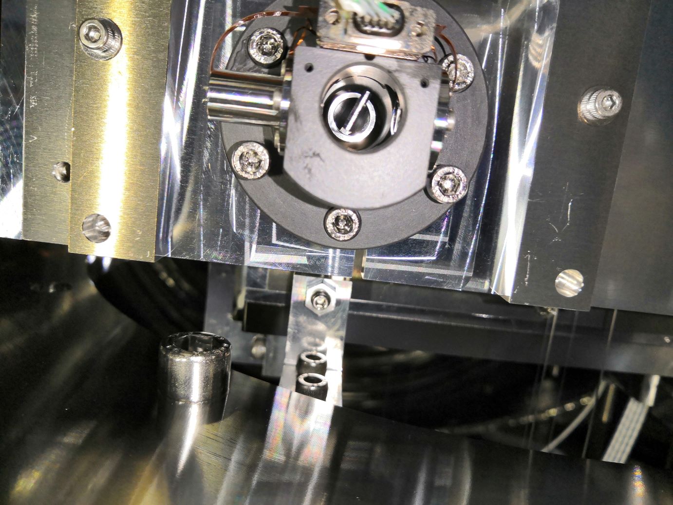
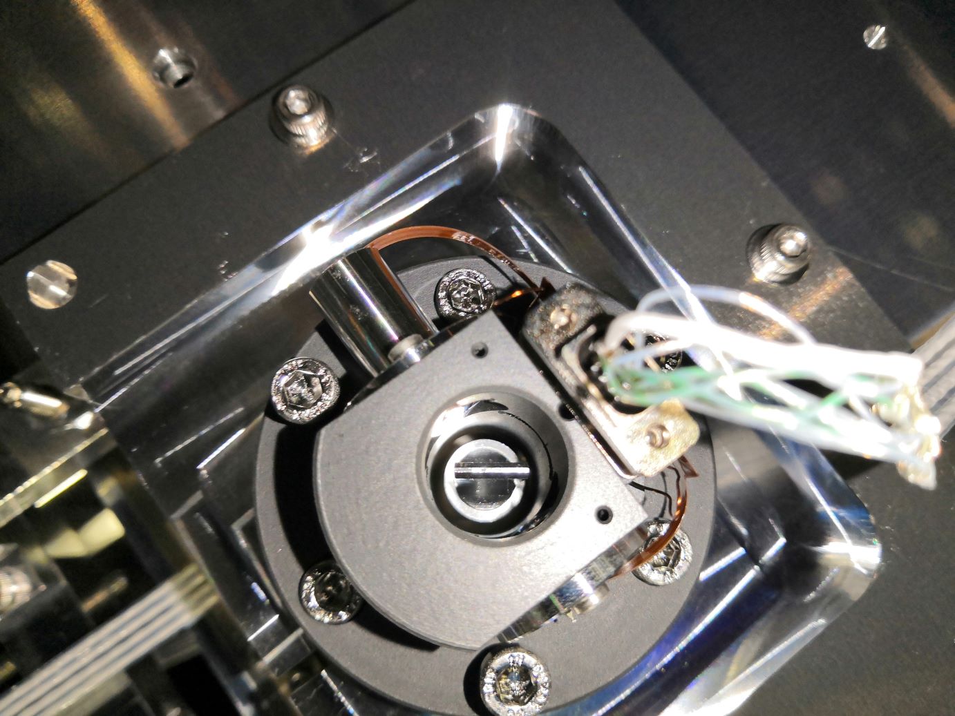
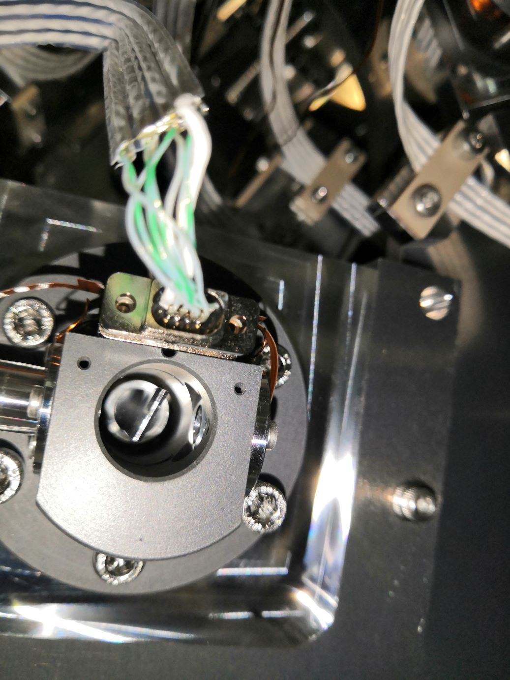
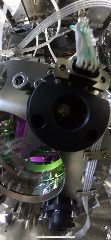
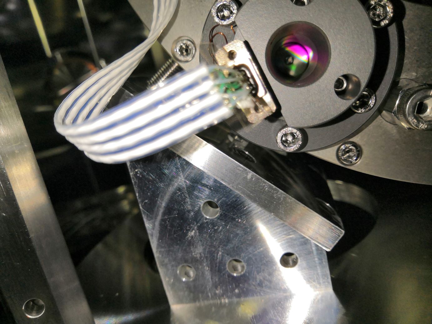
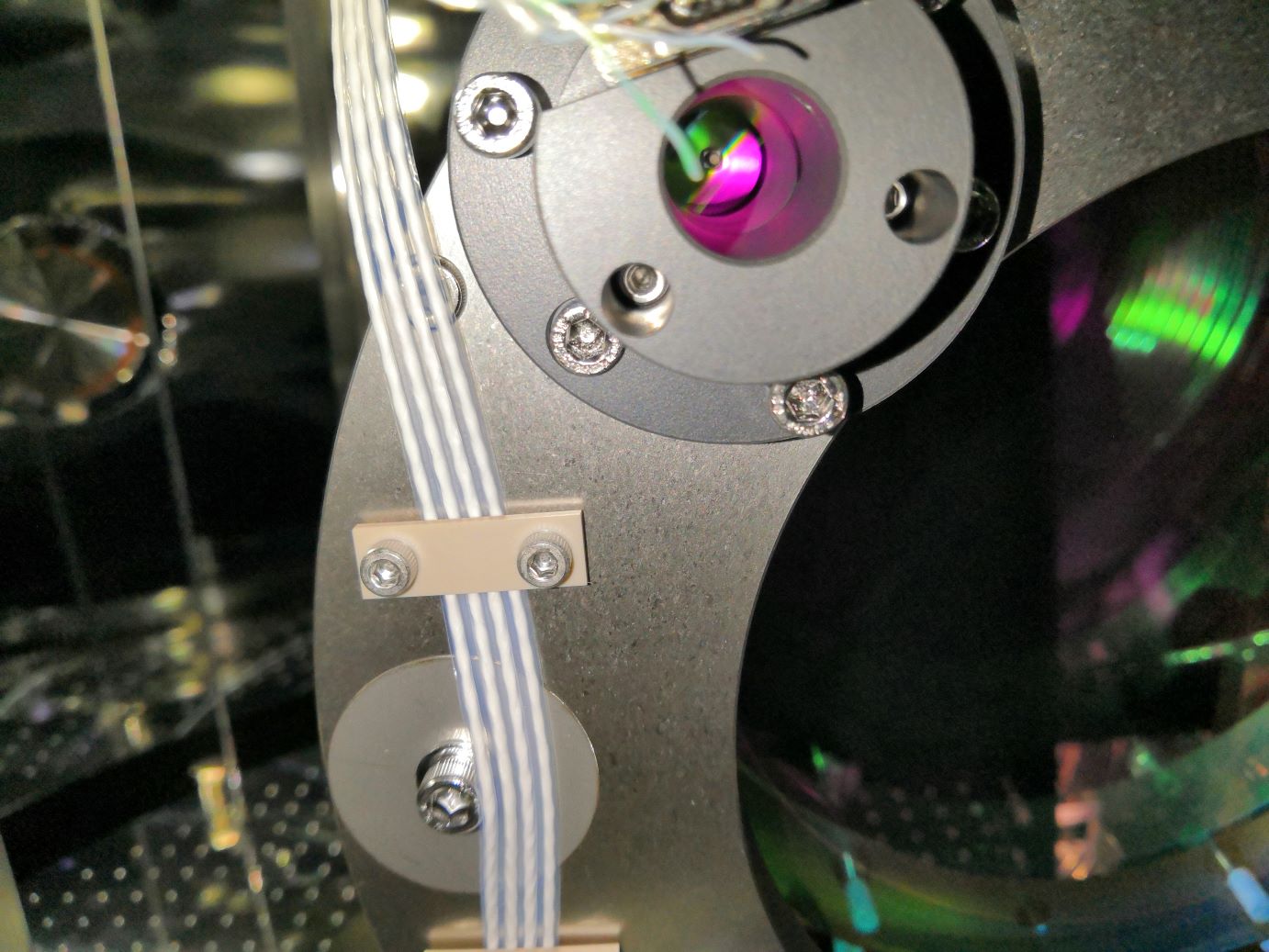
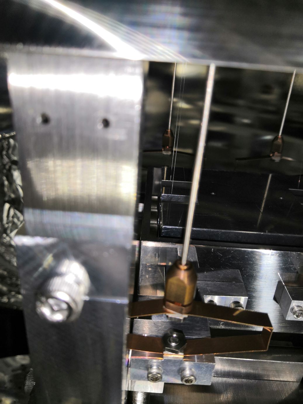
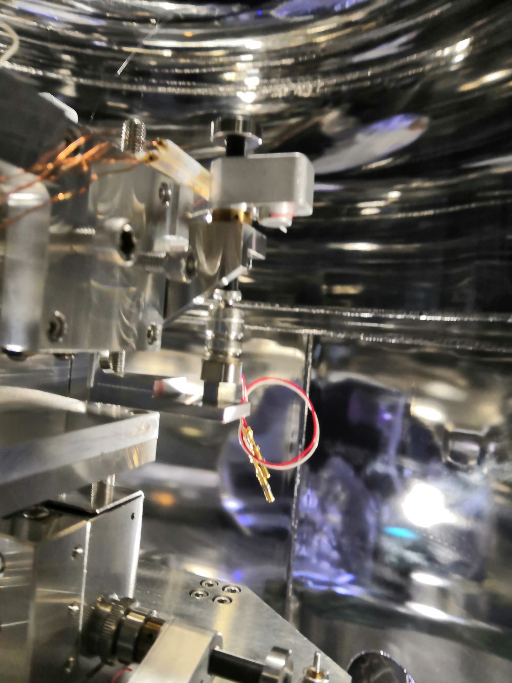
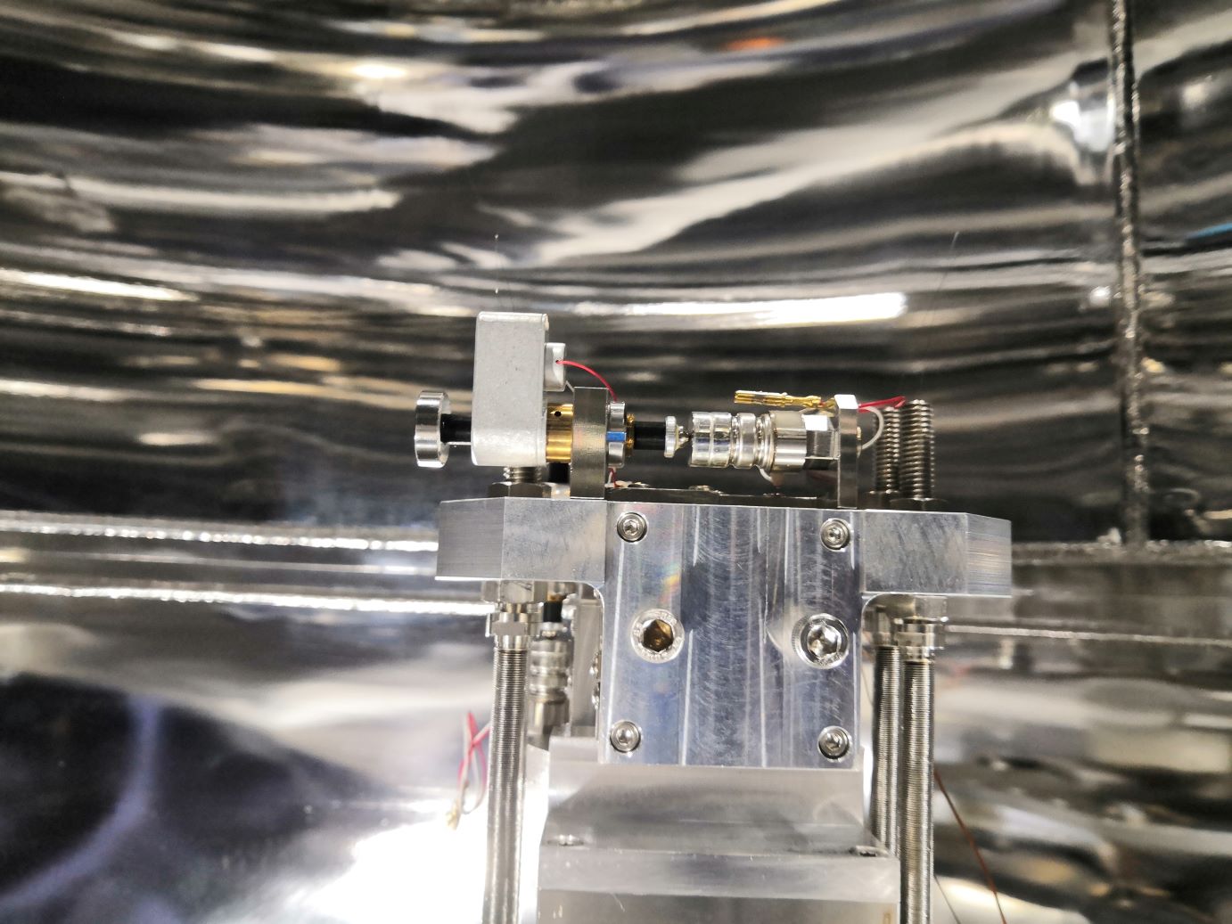
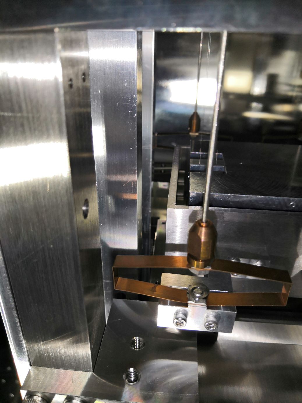
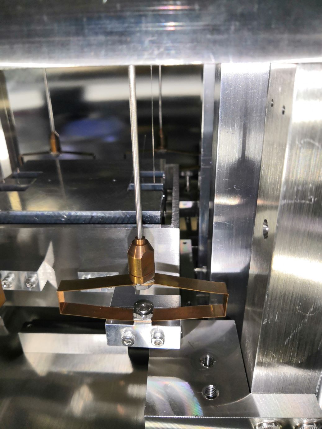
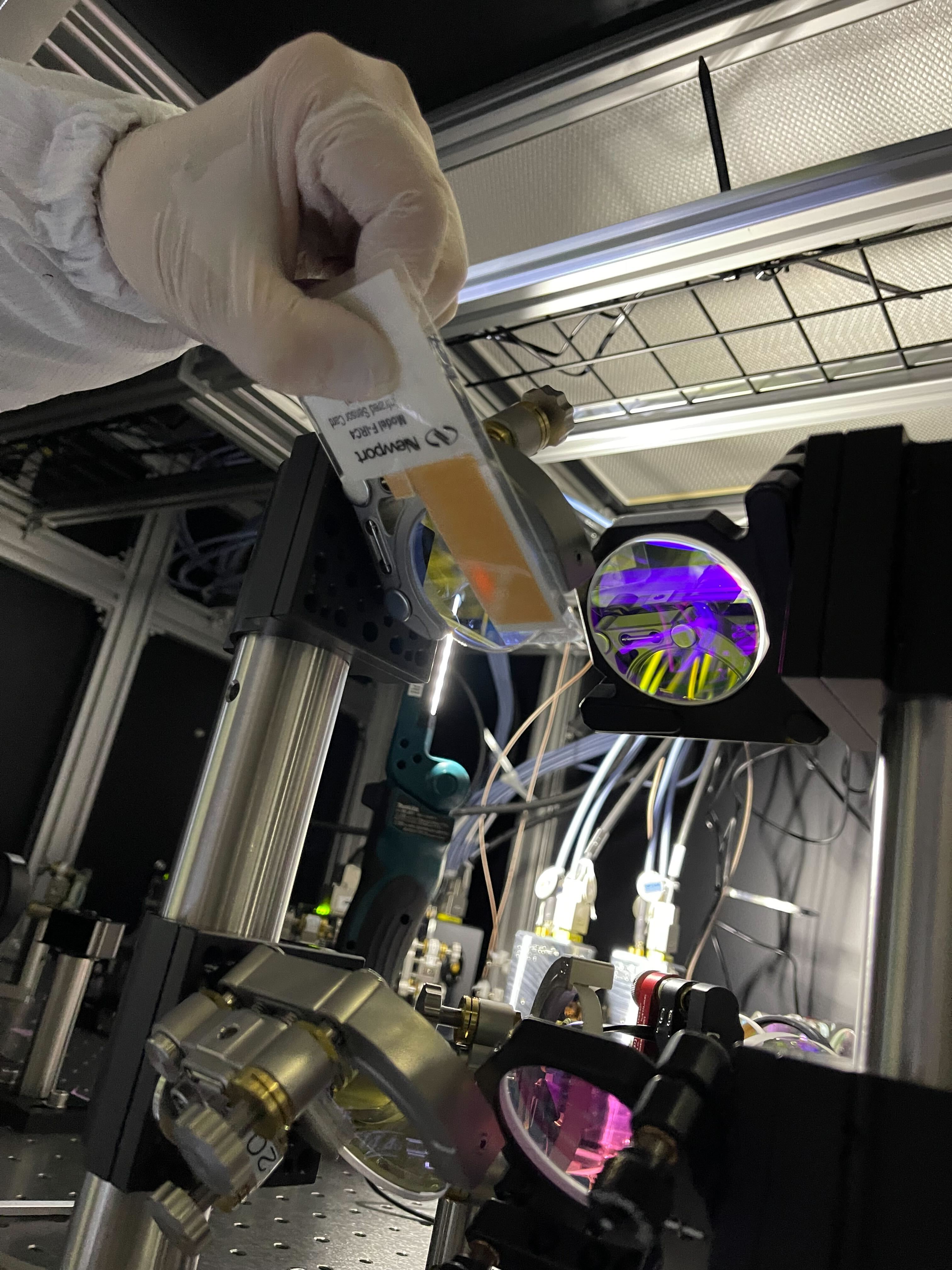
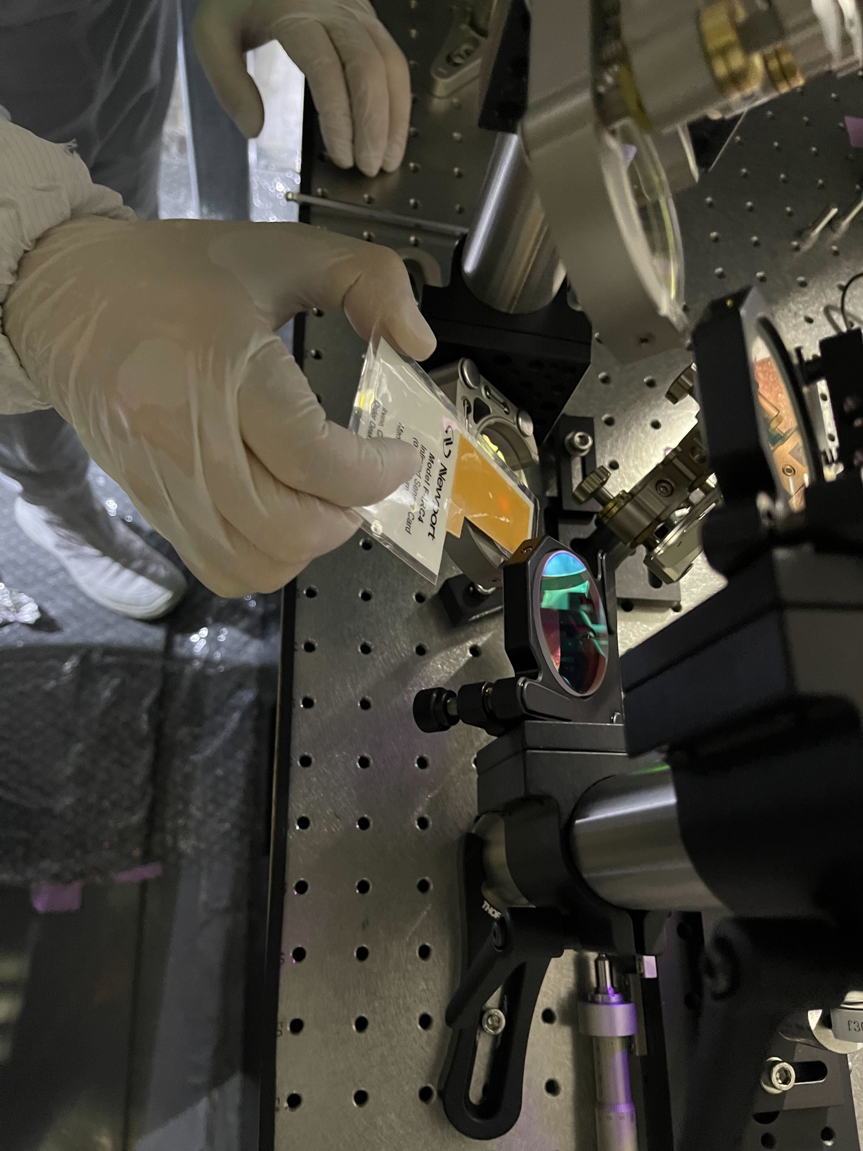
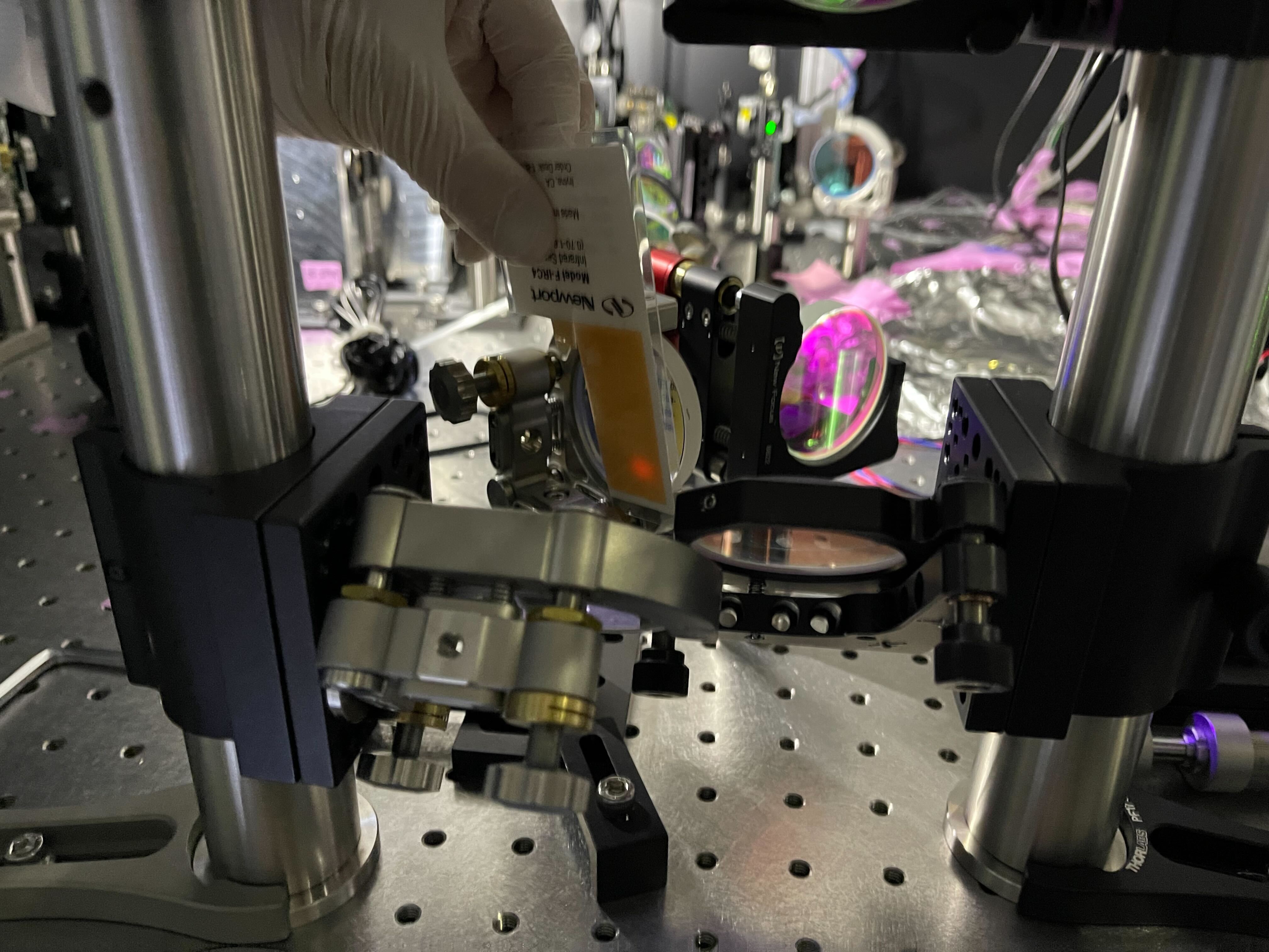
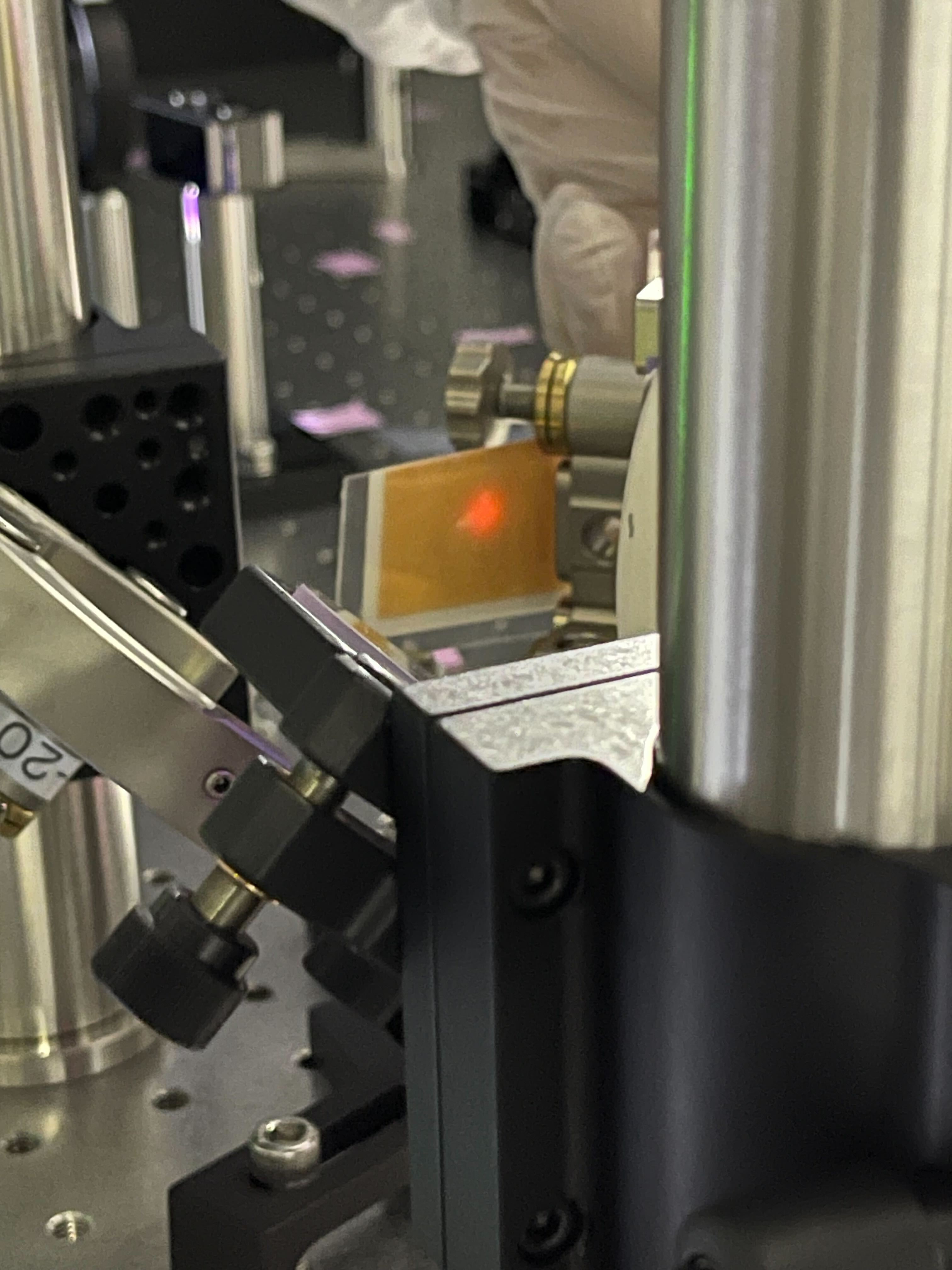
We performed the fine adjustment for the Pcal-X alignment with the ALIGNED state of the ETMX suspension.
We used PCAL_EX1(in Tx module) and PCAL_EX2(in EXA chamber) picomotors to adjust the path 1 so that the paths passed through the design position on the ETM and the center of the RxPD.
We left the Pcal-X laser ON, and the Pcal-X guardian state at OFS_CLOSED_LOW_POWER.
Attached files are showing beam positions on ETM and RxPD.
The total picomotor steps we requested are:
- PCAL_EX1, pico 2 (path 1 yaw): -550
- PCAL_EX2, pico 1(path 1 yaw): -600
- PCAL_EX2, pico 2(path 1 pitch): +400
- PCAL_EX2, pico 3(path 2 yaw): +100
- PCAL_EX2, pico 4(path 2 pitch): +300
The final optical efficiencies were (quick measurement):
- Path 1: 97.0%
- Path 2: 96.5%
- Path 1+2: 96.7%
These are similar to klog28820.
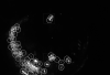
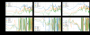
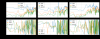
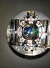
By analyzing the recent TCam images, I identified the mirror center of ETMX, ITMX, and ITMY. When the ETMY or GreenY is ready, we will try to take the ETMY image and identify the mirror center.
Details
- For ETMX, I had an accidental chance to take the TCam for ETMX illuminated by Greenx on 4/23 (during adjustment work of PR2). For ITMX and ITMY, the image was taken on 3/15 (klog#28863).
- Note that the ETMX image was taken after the evacuation an the ITMX and ITMY images were taken before the evacuation.
- ETMX
- fitting result
- overlay with previous reference center (Magenta shows the previous mirror edge and center. Yesllow shows the latest fitting result)
- From this analysis, I updated the fixed radiuss of 1243 pixel which was computed from the conversion factor of 10/113 = 0.0885 [mm/pixel]. This was evaluated from the metal-scale-insert test(klog#28843).
- ITMX
- fitting result
- overlay with previous reference center (Magenta shows the previous mirror edge and center. Yesllow shows the latest fitting result)
- From the metal-scale-insert test(klog#28843), I evaluated the conversion factor as 10/60 = 0.167 [mm/pixel]. Accordingly, the mirror radius could be 660 pixel. But, this estimation has large uncertainty. If one pixel changes in the estimation, the mirror radius changes 600~733 pixel. I decided to use the fixed radius of 630 pixel which we evaluated by hand fitting with Aogaku members previously, because this value has the small uncertainty than the metal-scale-insert test.
- ITMX
- fitting result
- overlay with previous reference center (Magenta shows the previous mirror edge and center. Yesllow shows the latest fitting result)
[Kimura and M. Takahashi]
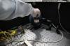
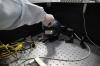
To identify the source of the liquid material that entered the EYA tank, three filters of the air compressor and the inside of the connection piping of the dry pumps for vacuum pumping were visually inspected.
As a result of the visual inspection, no traces of liquid material were found inside the filters of the air compressor and the connecting piping of the dry pumps for vacuum pumping.
The smell inside the filter and piping was confirmed by nose, but the same irritating smell observed in the EYA tank was not found.
Three filters of the air compressor were replaced with new ones because more than two years had passed since the last replacement.
I have already made segments that excludes the IPC error segments from the science mode.
/home/detchar/Segments/K1-GRD_SCIENCE_MODE_NO_IPC_ERROR
[Kimura and Ueda (SKS) ]
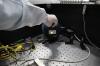
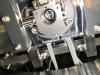
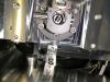
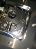
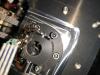
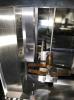
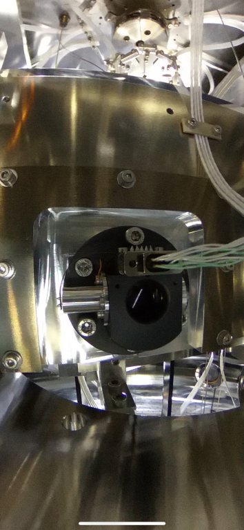
On the afternoon of 18 Apr., Ueda-san and me performed a vacuum leak test for new pressure gage of GVetmx.
The results of the vacuum leak test confirmed that the new pressure gage of GVetmx did not leak more than 1x10^-12 Pam^3/s.
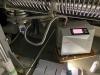
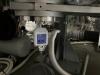
[Kimura, and M. Takahasshi]
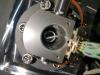
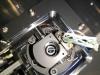
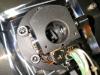
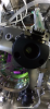
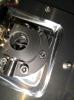
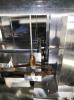
On the morning of 25 Apr., M. Takahashi-san and me performed a vacuum leak test for new pressure gage of GVetmy.
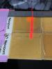
(See attached photos 1~2)
The results of the vacuum leak test confirmed that the new pressure gage of GVetmy did not leak more than 1x10^-12 Pam^3/s.
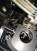
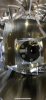
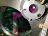
After the leak test, we set up protection panel in front of the gage.
(See attached photo 3)
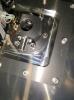
The protection panel for the gage of GVetmx was set up, too.
Uchiyama
I turned on 4 TMPs to pump down IXC at around 9:45.
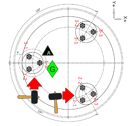
[YokozaWashimi, Ishikawa, Ozaki, Sudo]
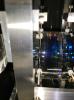
We performed hammering tests (vertical tapping) for the OMC in-vac table.
The tapped points are the table, the base plate, and the ground near the stack1 or 2.
Yamamoto, Tanaka
We modified the setting from 'Zero_histroy' mode to 'Always_on' mode in the COILOUTF filters for all of suspensions.
Also, we loaded the setting for all COILOUTF filters around 13:30 JST 4/25 2024, except for ETMX, ITMY, PRM, PR2 which someone use in this time.
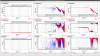
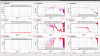
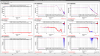
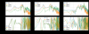
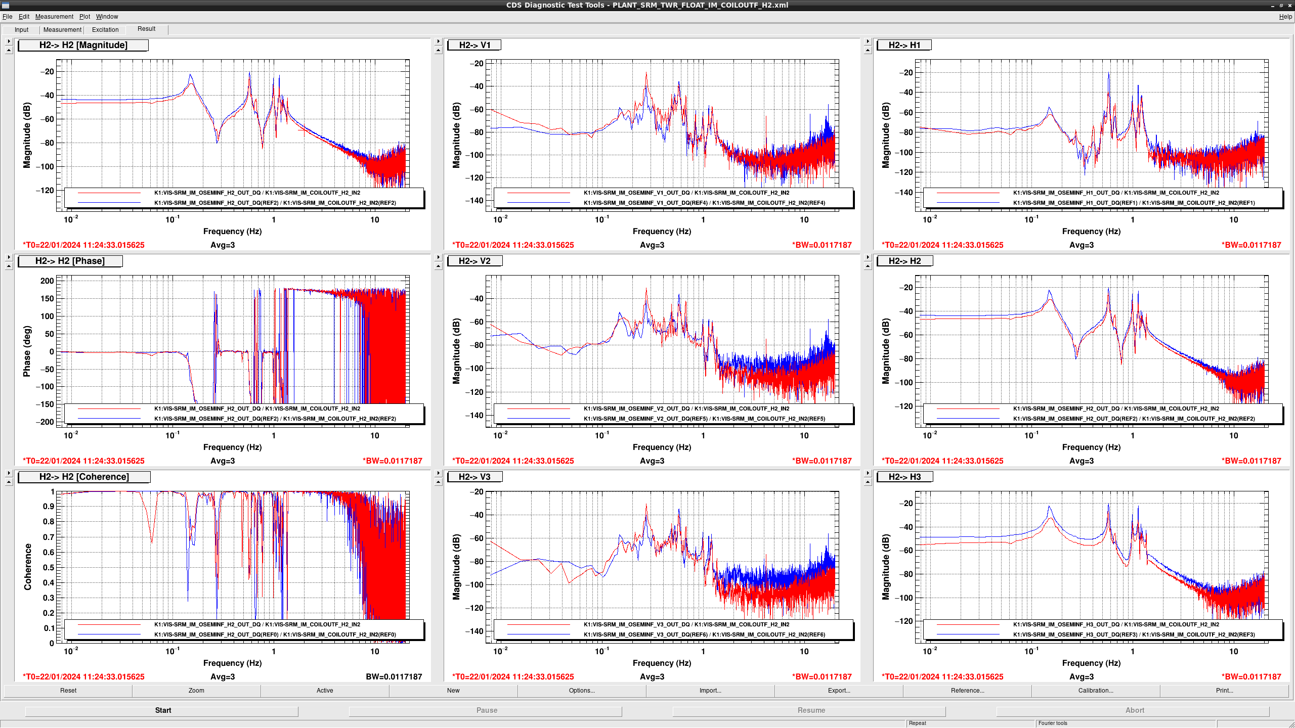
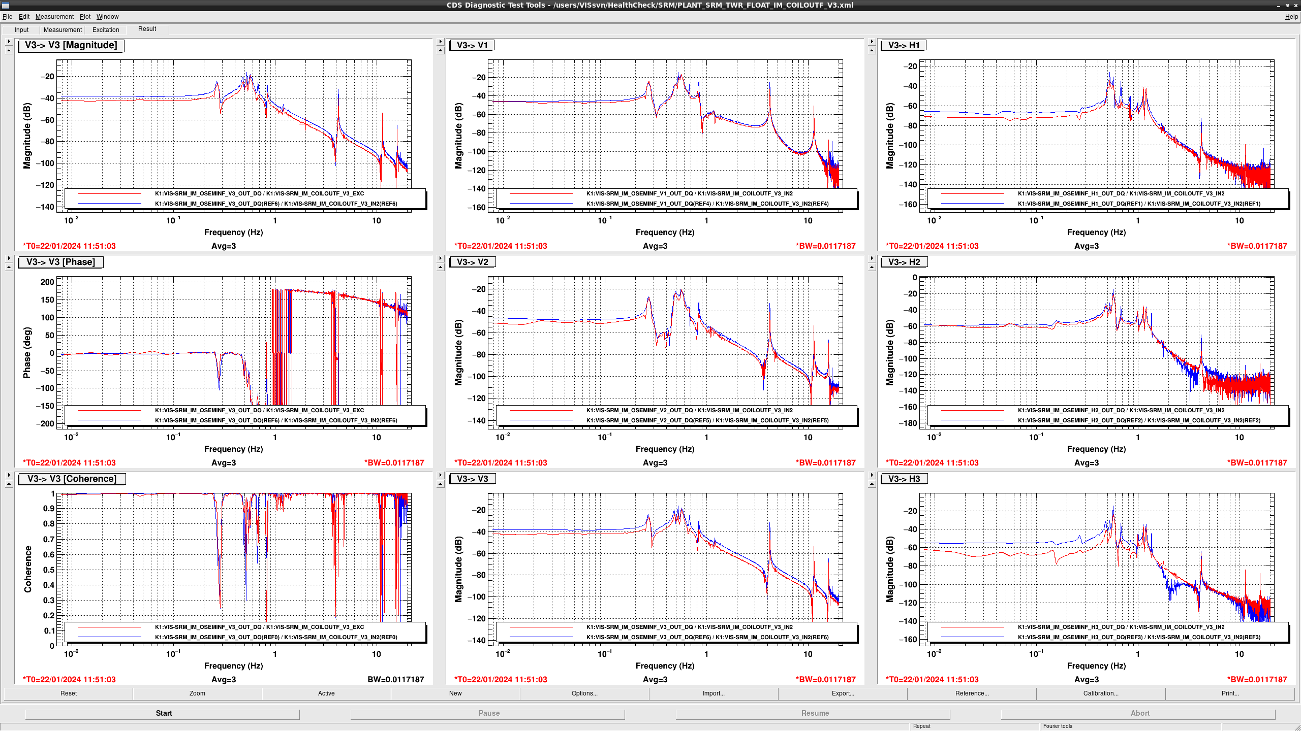
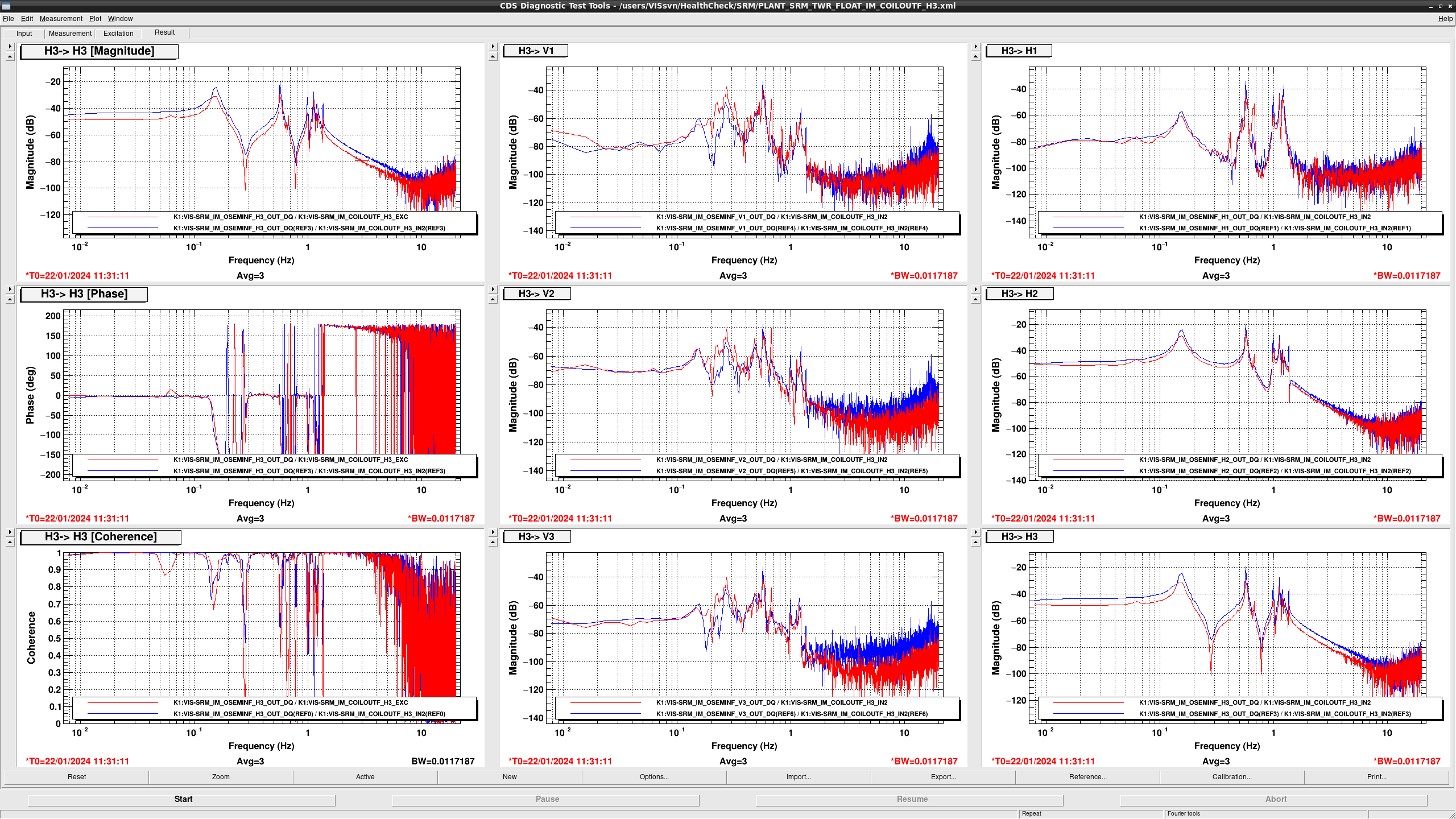
According to the health check in January, gain of OSEM #3 (H2) and #4 (V3) are 3 dB and 5 dB smaller than before the earthquake, respectively (fig1 and 2).
Note:
Somehow, SRM IM OSEM TFs have lower gain (2-5 dB) than before the earthquake not only in H2 and V3 but also the others (fig3: case of H3).
Further investigation is necessary.
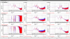

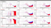
According to the health check in January, gain of OSEM #1 (H3) has almost no change before and after the earthquake.
According to the health check in January, gain of OSEM #2 (H1) is about 1dB smallerthan before the earthquake (fig1).

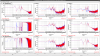
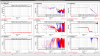
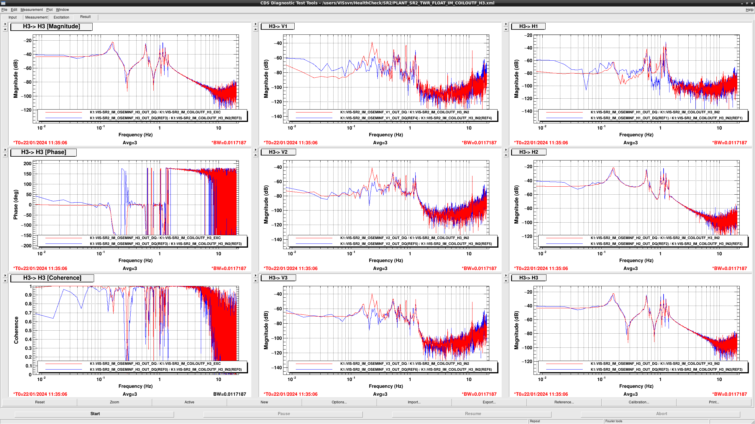
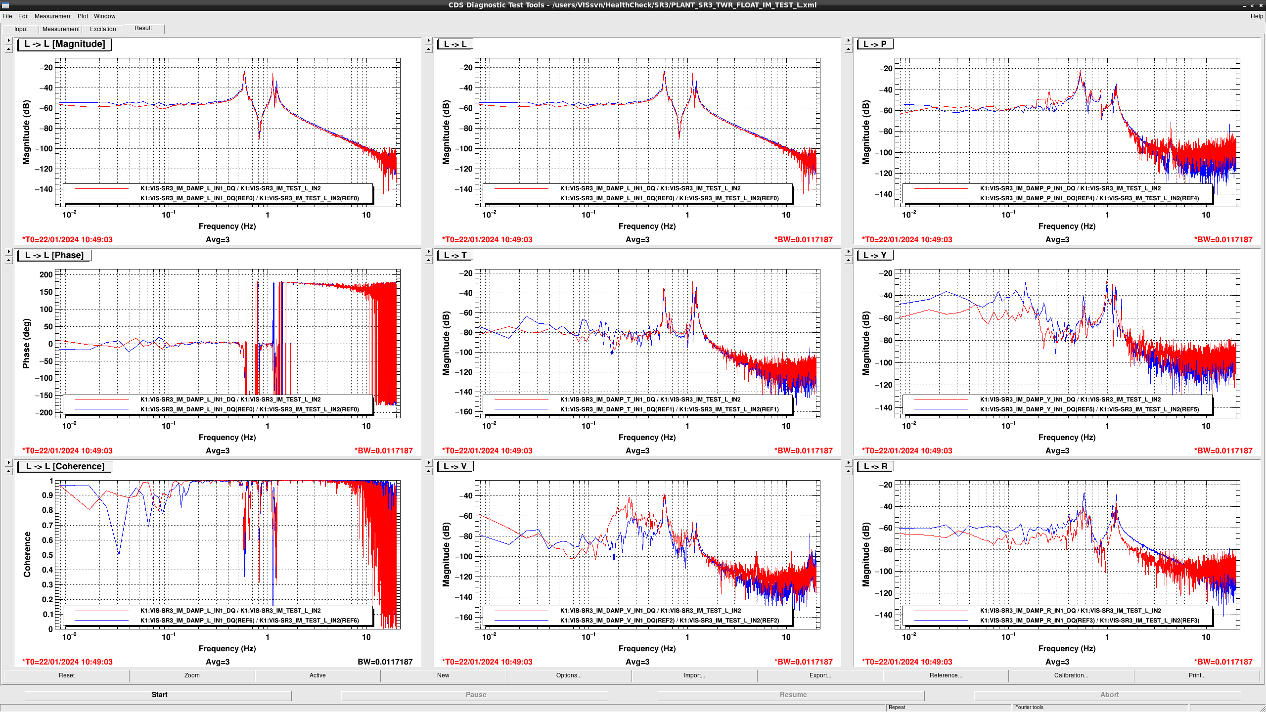
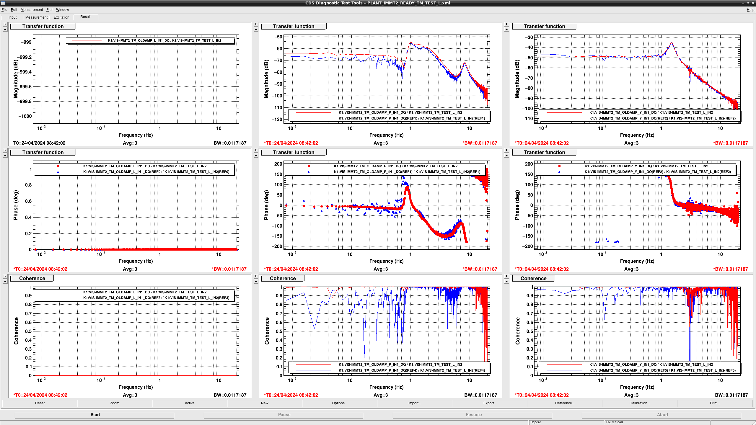
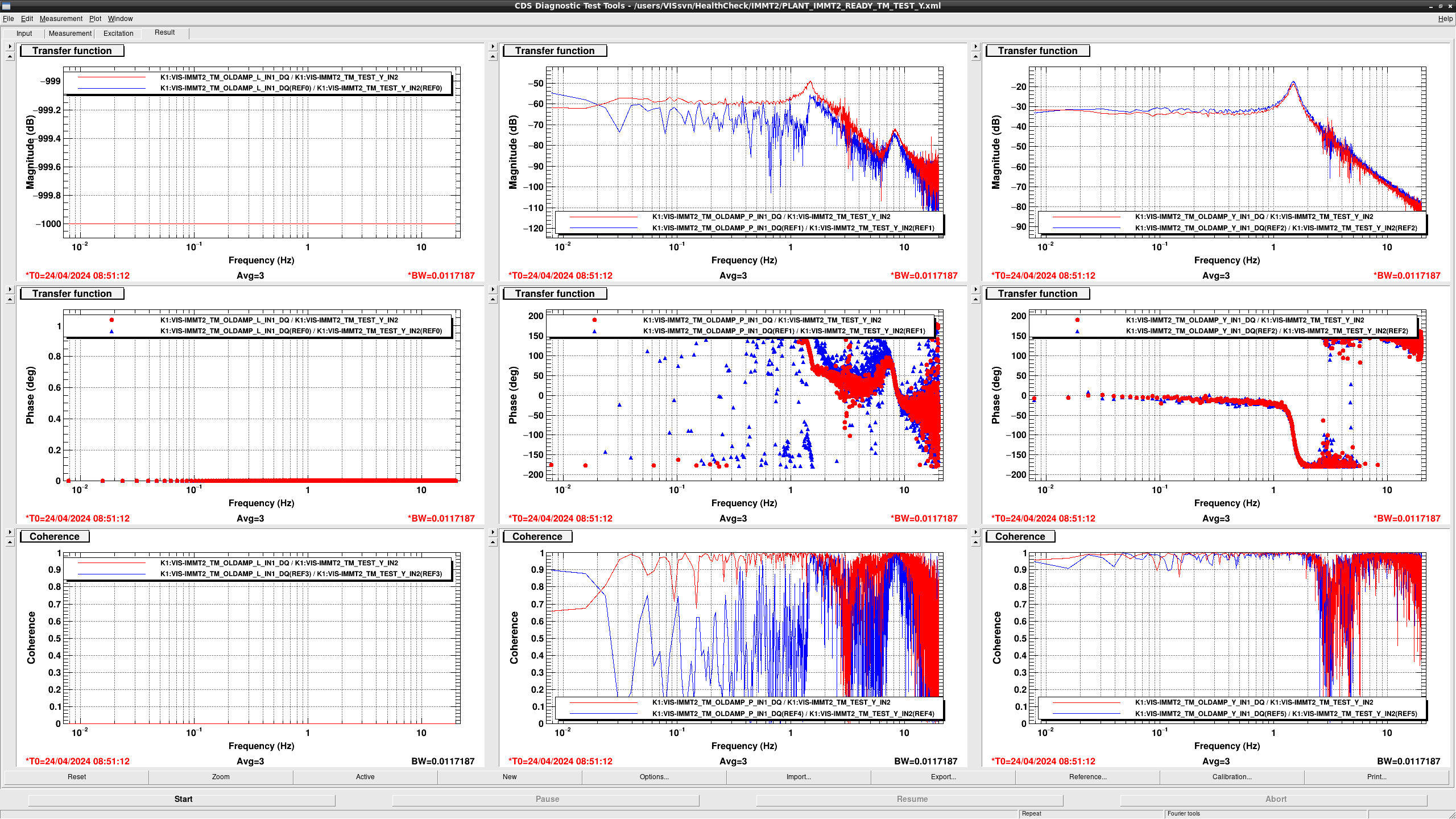
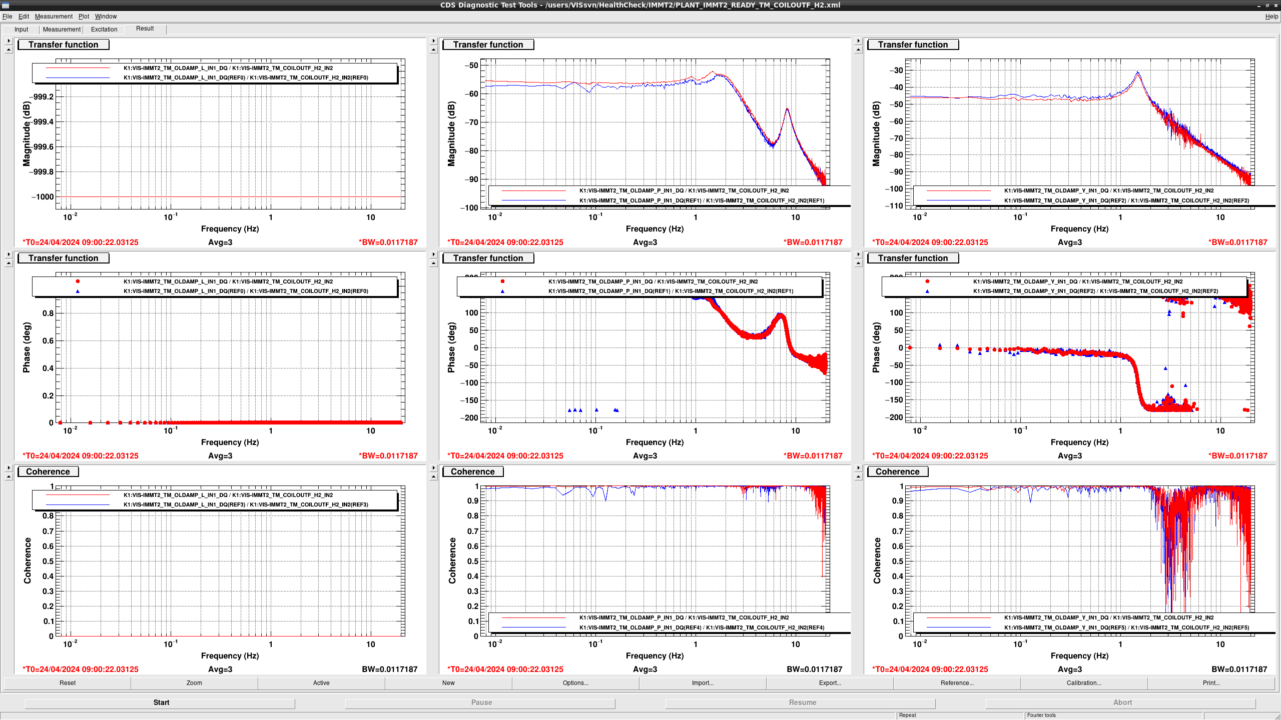
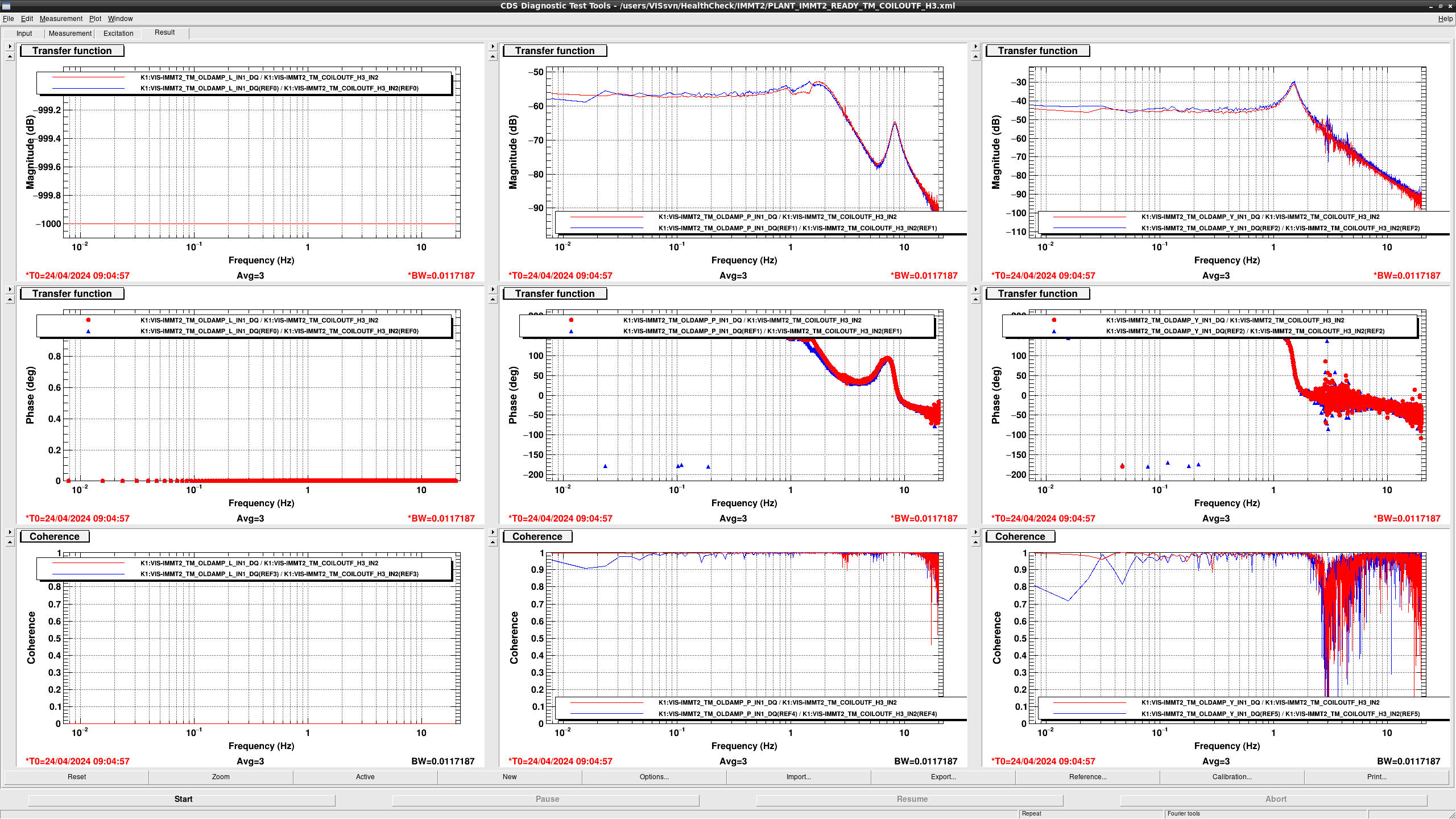
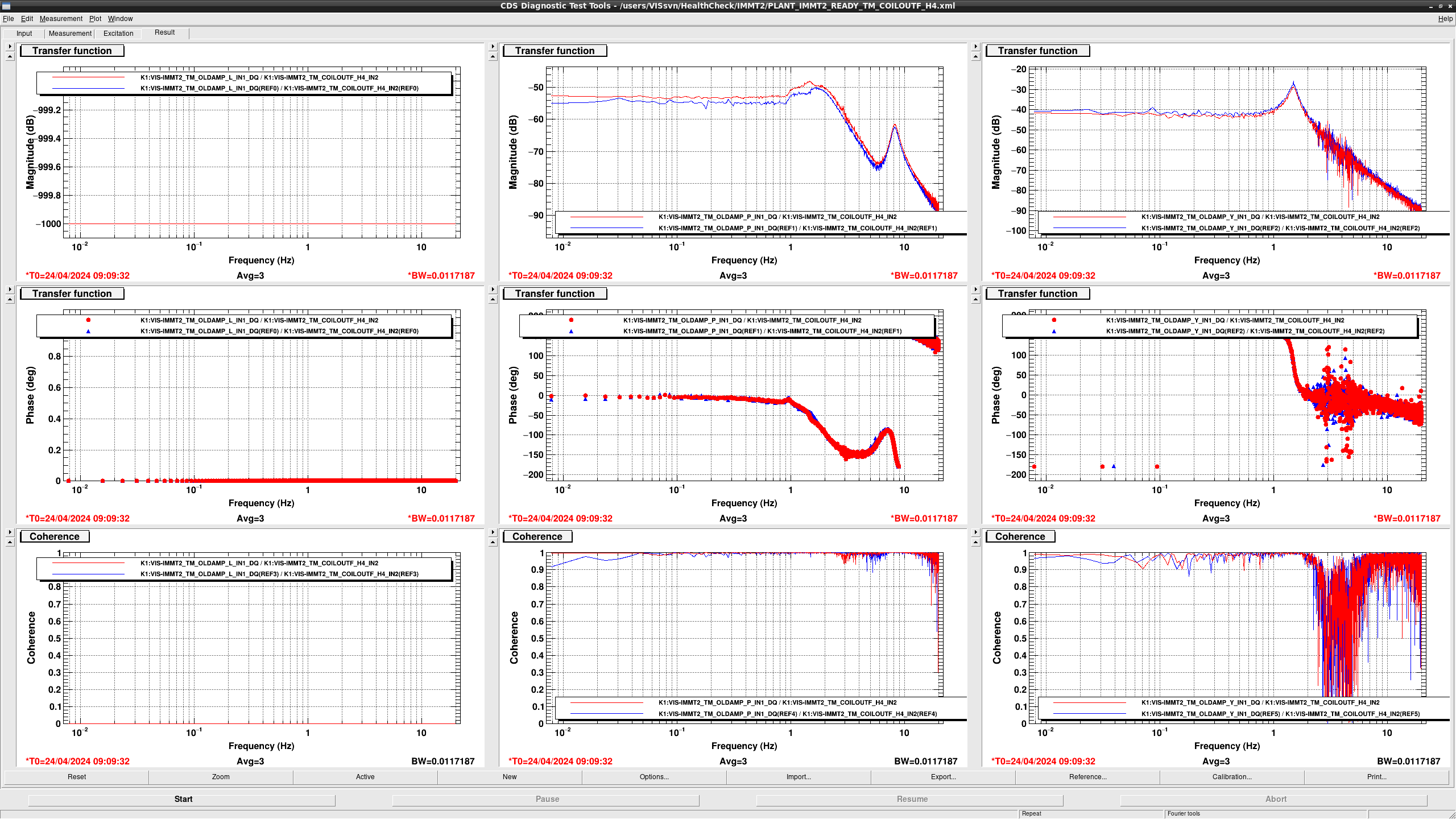
I performd health check of IMMT2 (fig1 - fig7).
All TFs seem fine.
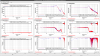

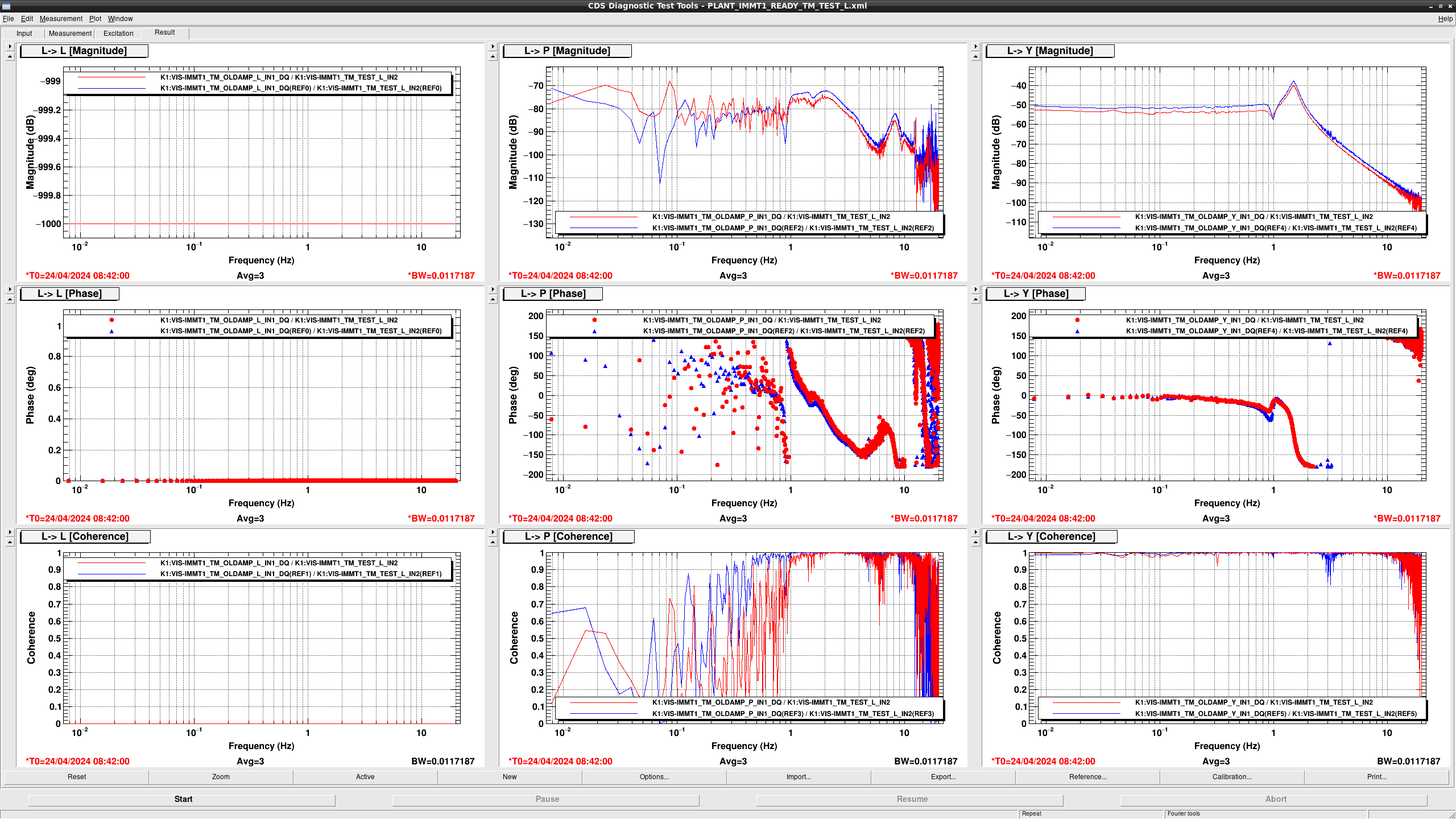
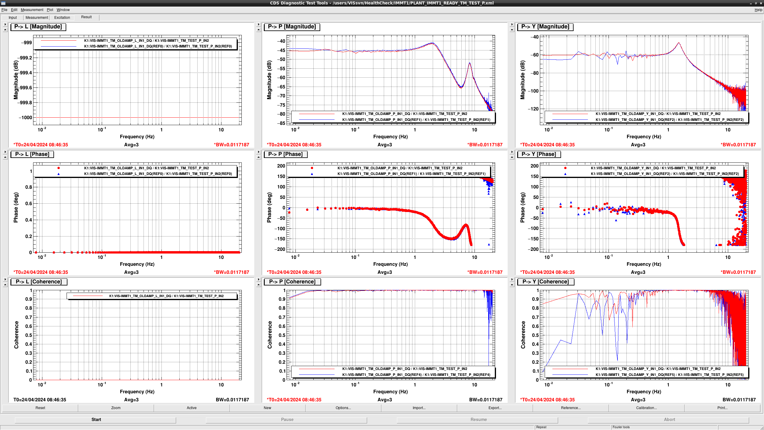
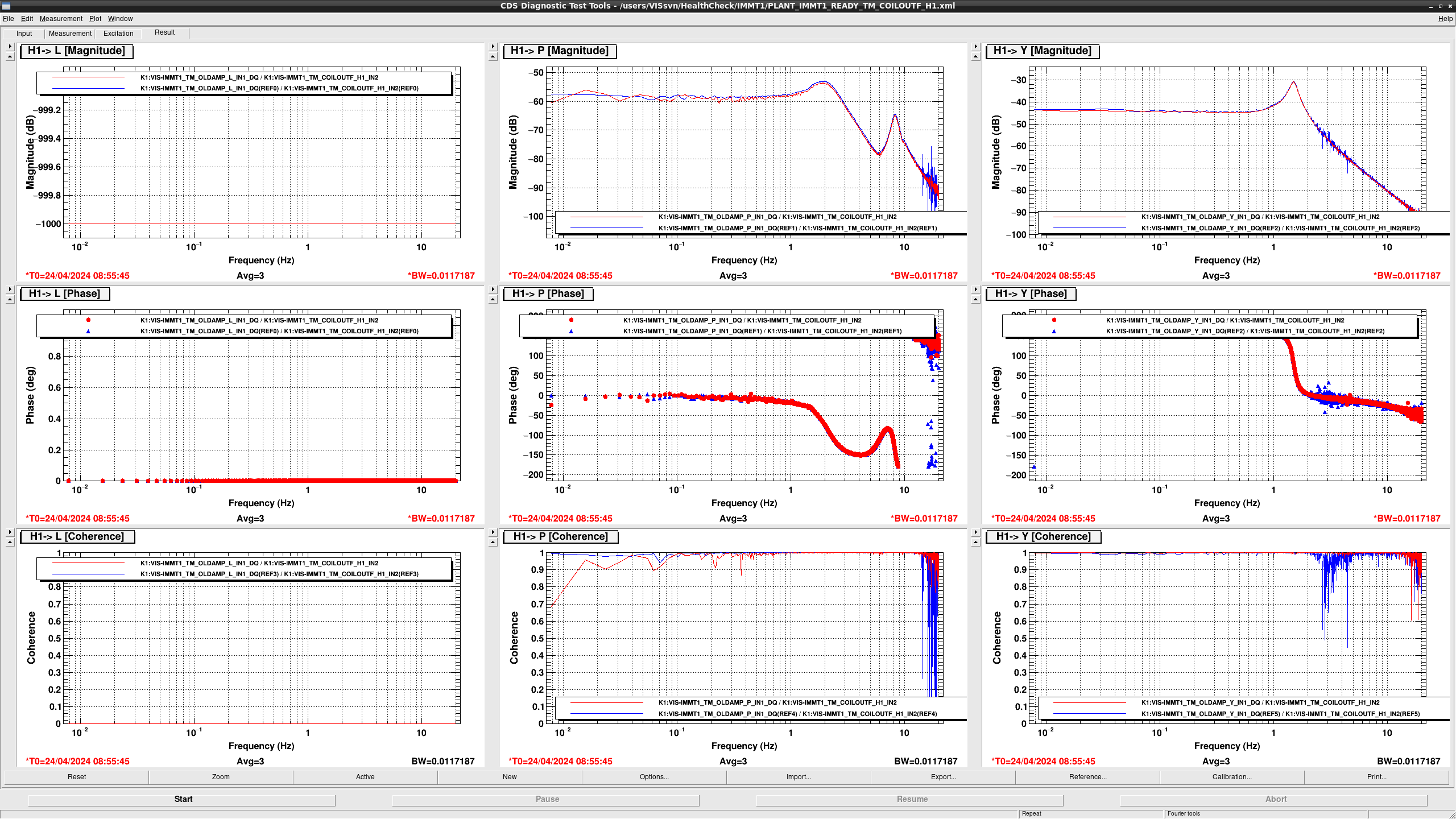
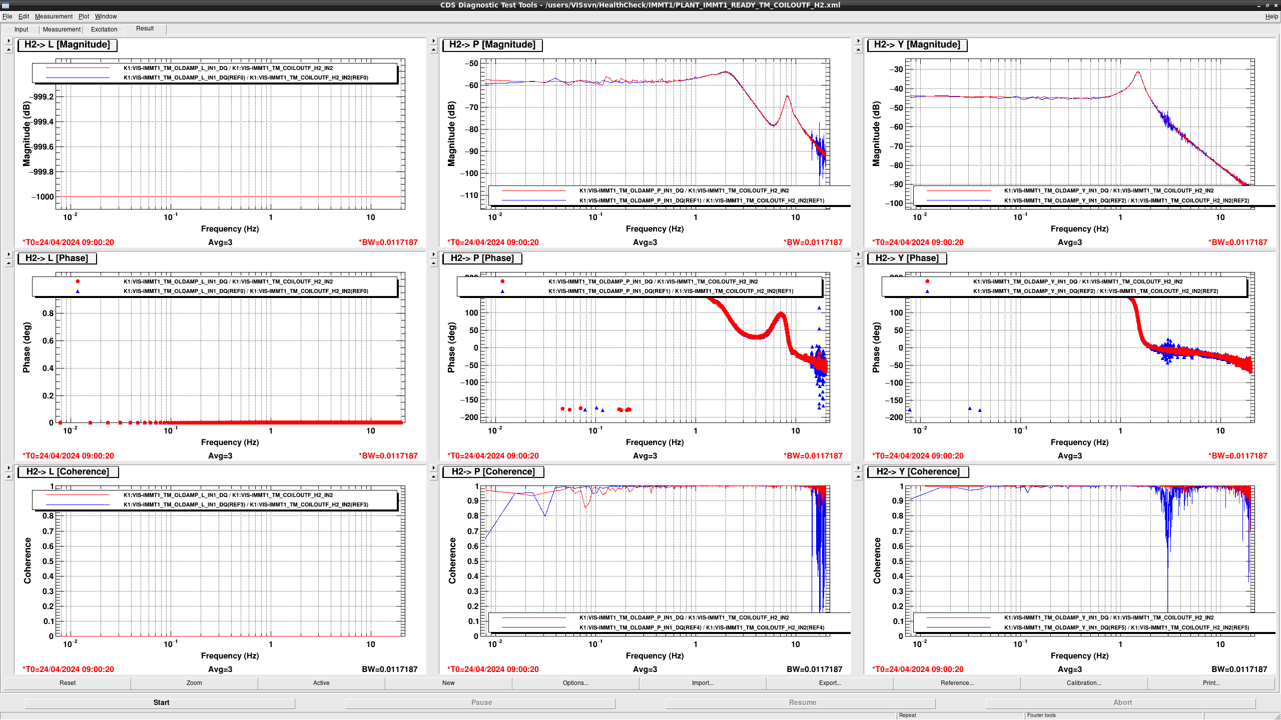
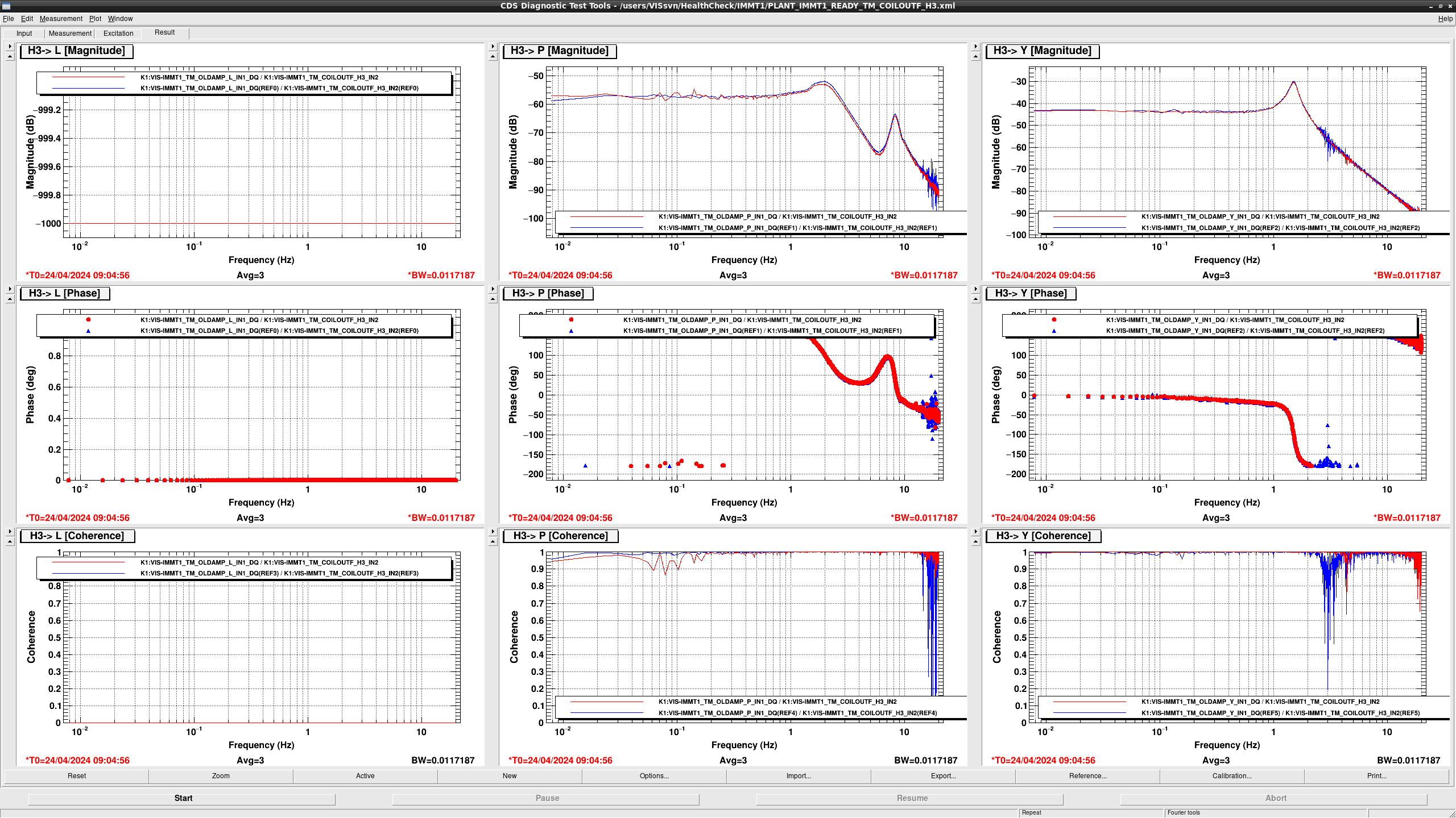
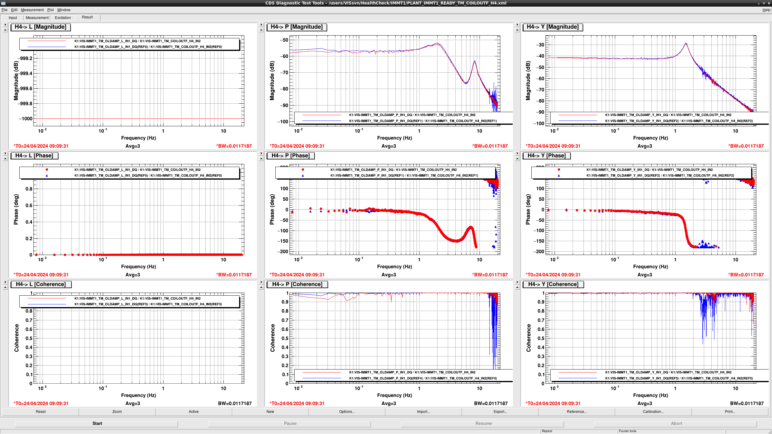
I performd health check of IMMT1 (fig1 - fig7).
All TFs seem fine.

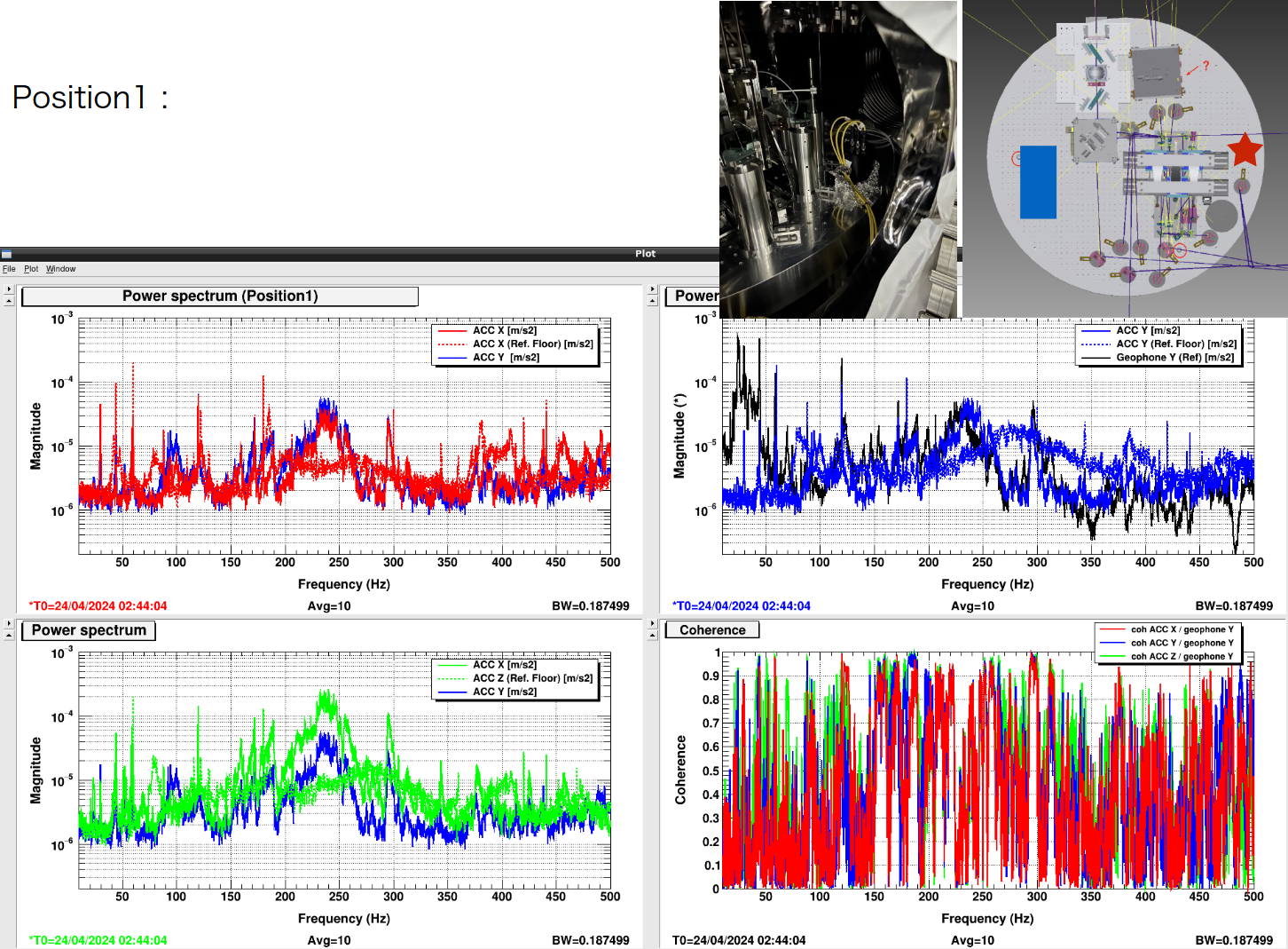
We performed the measurement of the vibration spectrum using the 3axis accelerometer.
Totally, 10 position measurement were performed.
The summary will be appeared soon.
[Ikeda, Takahashi]
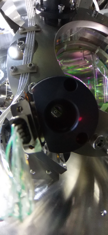
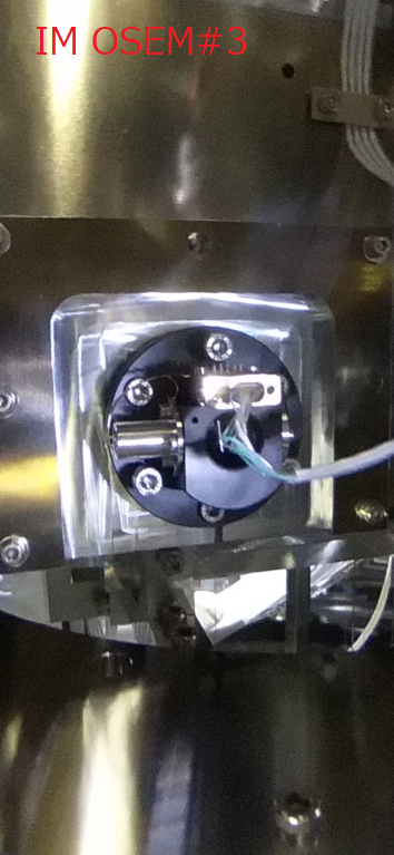
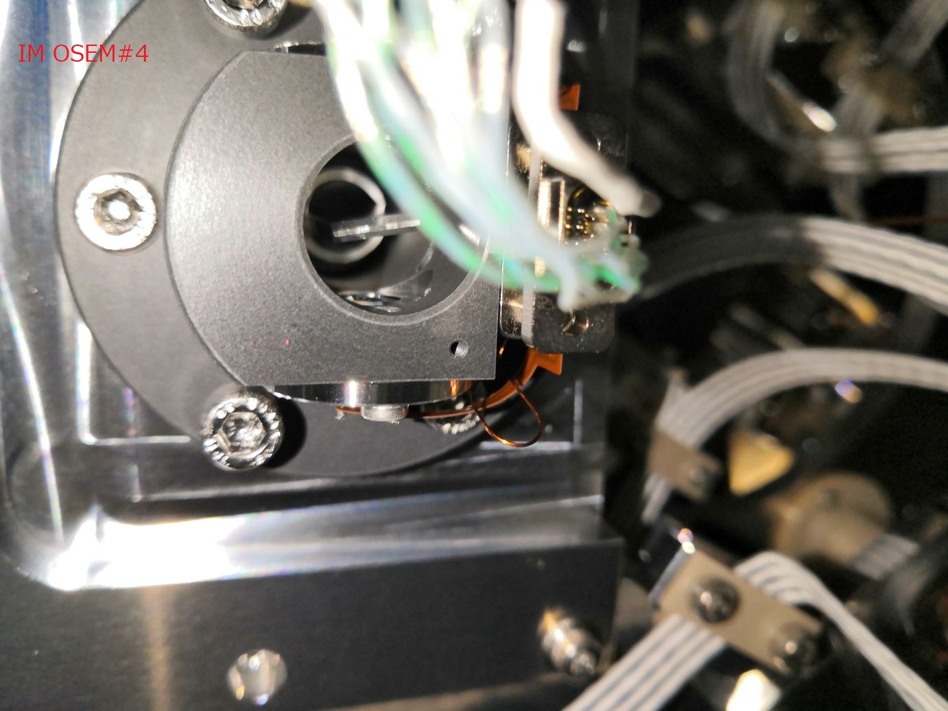
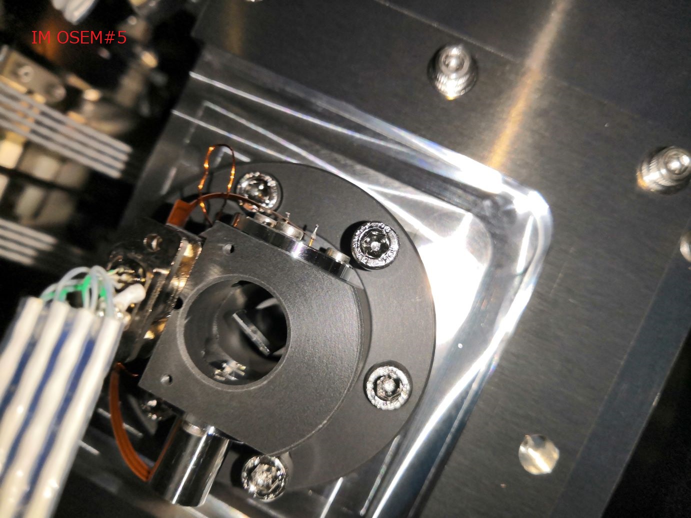
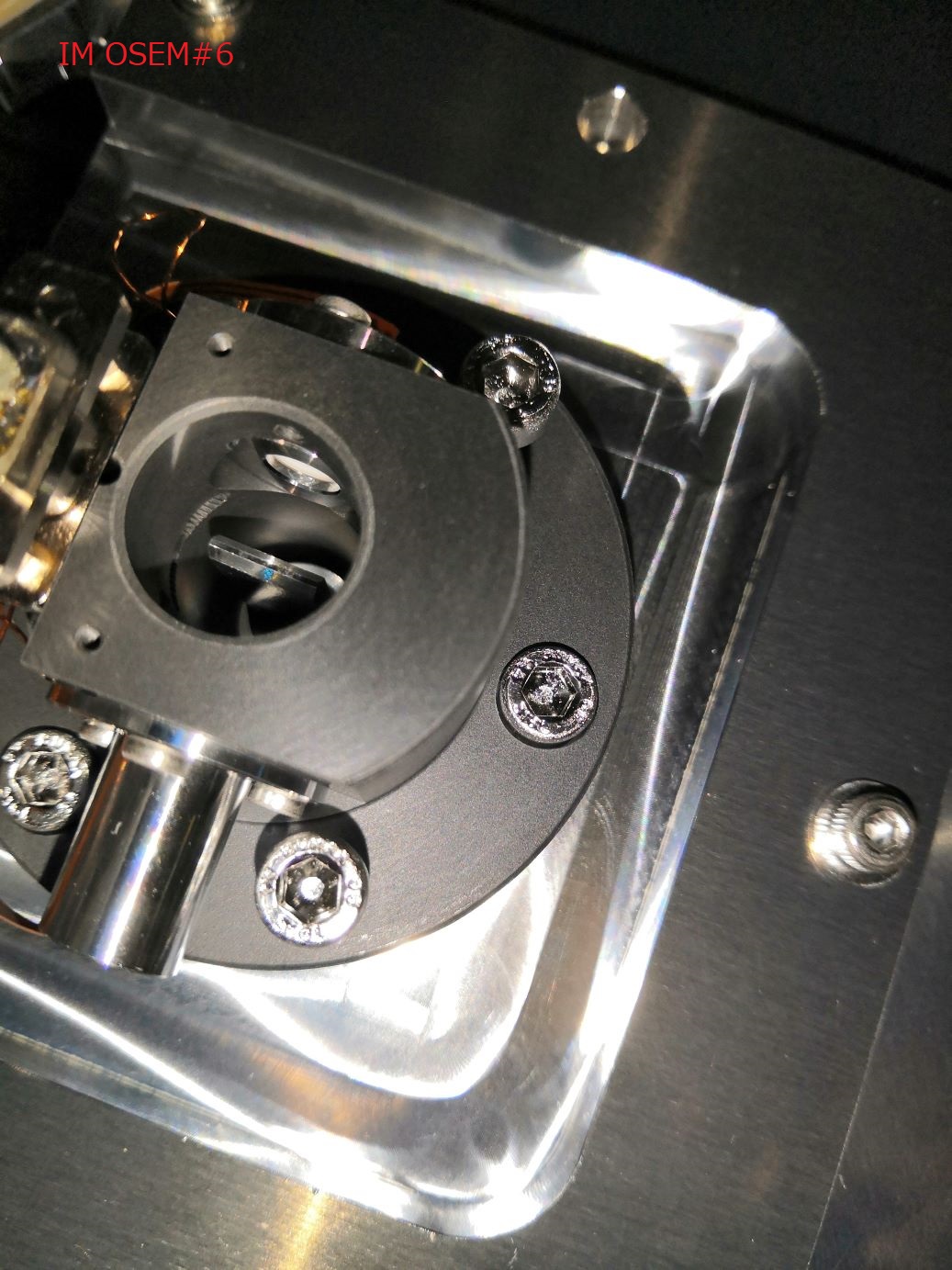
We checked the OSEMs visually. The flap of OSEM#3 and #4 in the IM was rotated more than 40°.


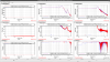
According to the health check in January, gain of OSEM #3 (H2) and #4 (V3) are 3 dB and 5 dB smaller than before the earthquake, respectively (fig1 and 2).
Note:
Somehow, SRM IM OSEM TFs have lower gain (2-5 dB) than before the earthquake not only in H2 and V3 but also the others (fig3: case of H3).
Further investigation is necessary.
[Ikeda, Takahashi]
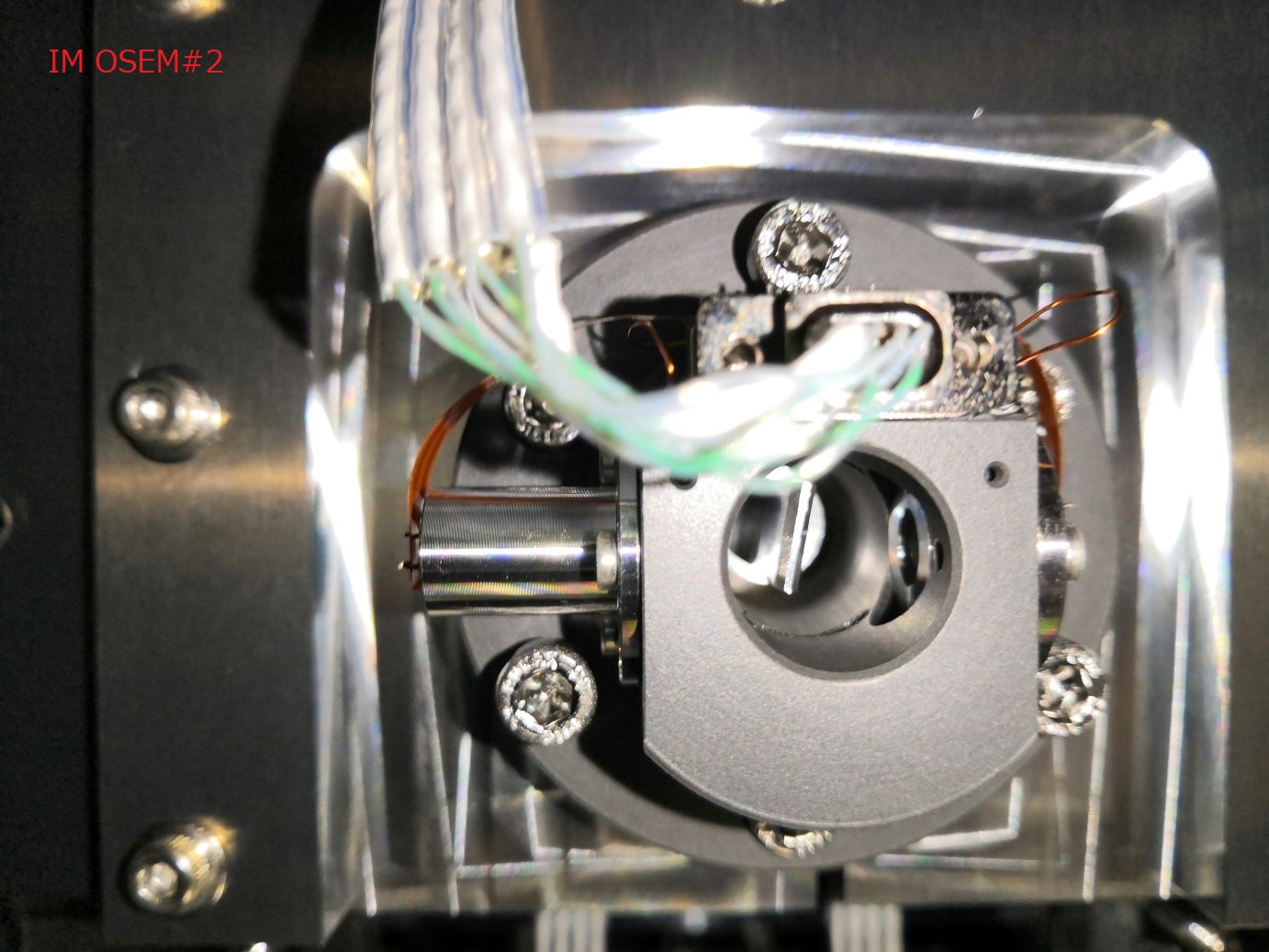
We checked the OSEMs visually. The flap of OSEM#2 in the IM was rotated more than 40°.

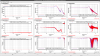
According to the health check in January, gain of OSEM #2 (H1) is about 1dB smallerthan before the earthquake (fig1).
[Ikeda, Takahashi]
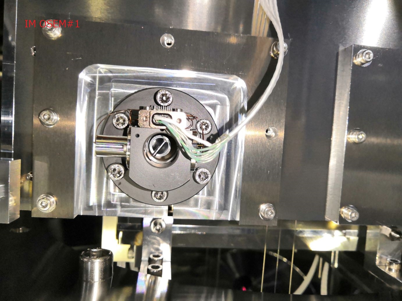
We checked the OSEMs visually. The flap of OSEM#1 in the IM was rotated more than 40°.


According to the health check in January, gain of OSEM #1 (H3) has almost no change before and after the earthquake.
[Takahashi, Ikeda, Hirata, Ushiba]
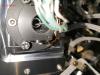
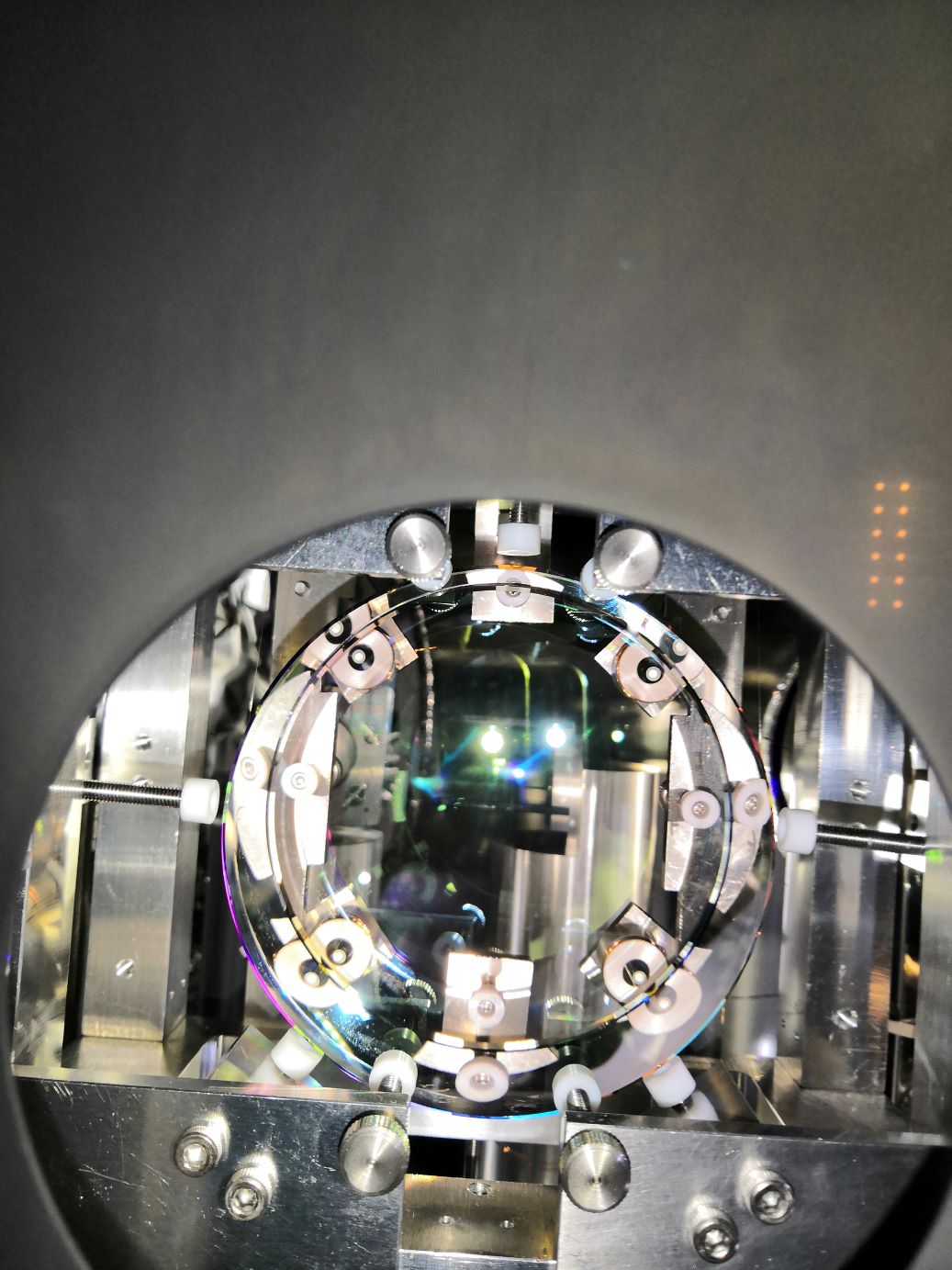
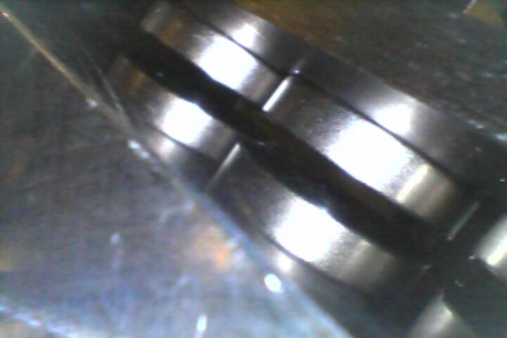
We checked the IMMT2 suspension visually. There was a small margin of the Pico-motor range for the pitch direction. There was no margin for yaw CCW direction (<1mm). There were not any rubbing magnets in the IM.


[Takahashi, Ikeda, Hirata, Ushiba]
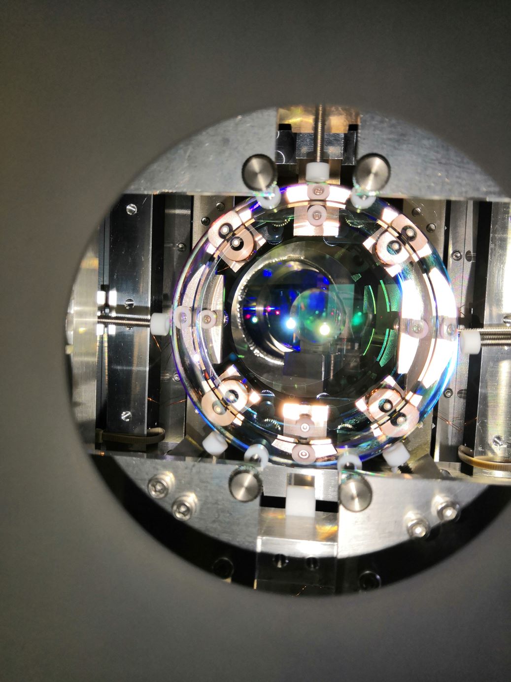
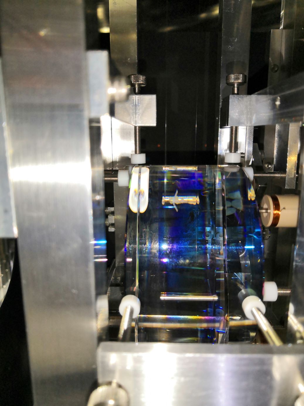
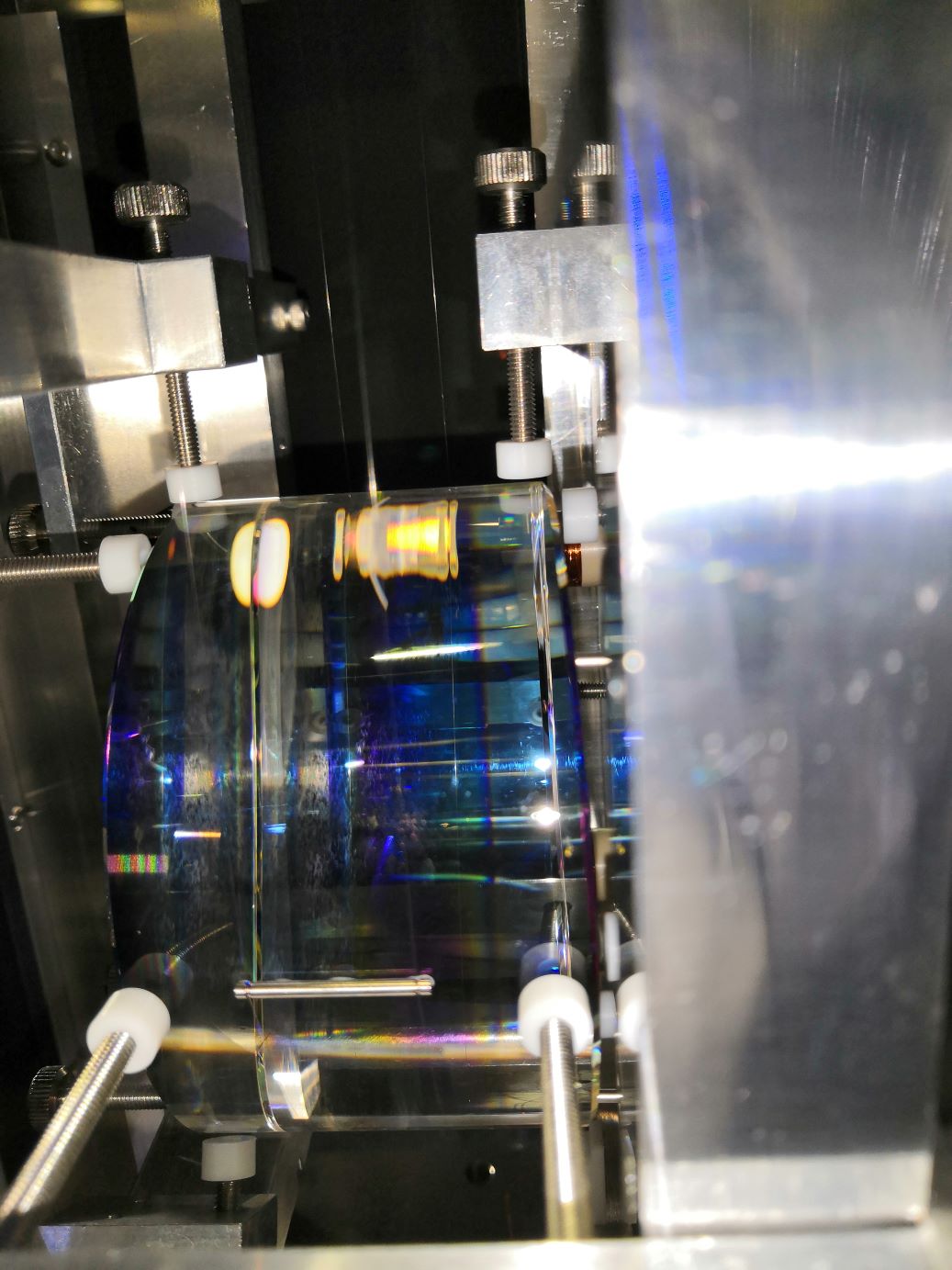
We checked the IMMT1 suspension visually. There were margins of the pico-motor range much enough to adjust both pitch and yaw motion. There were not any rubbing magnets in the IM. When we took the pictures with a fiber scope touching the EQ stop frame, the TM pitch jumped due to a weak joint in the X-Y stage supporting the frame.


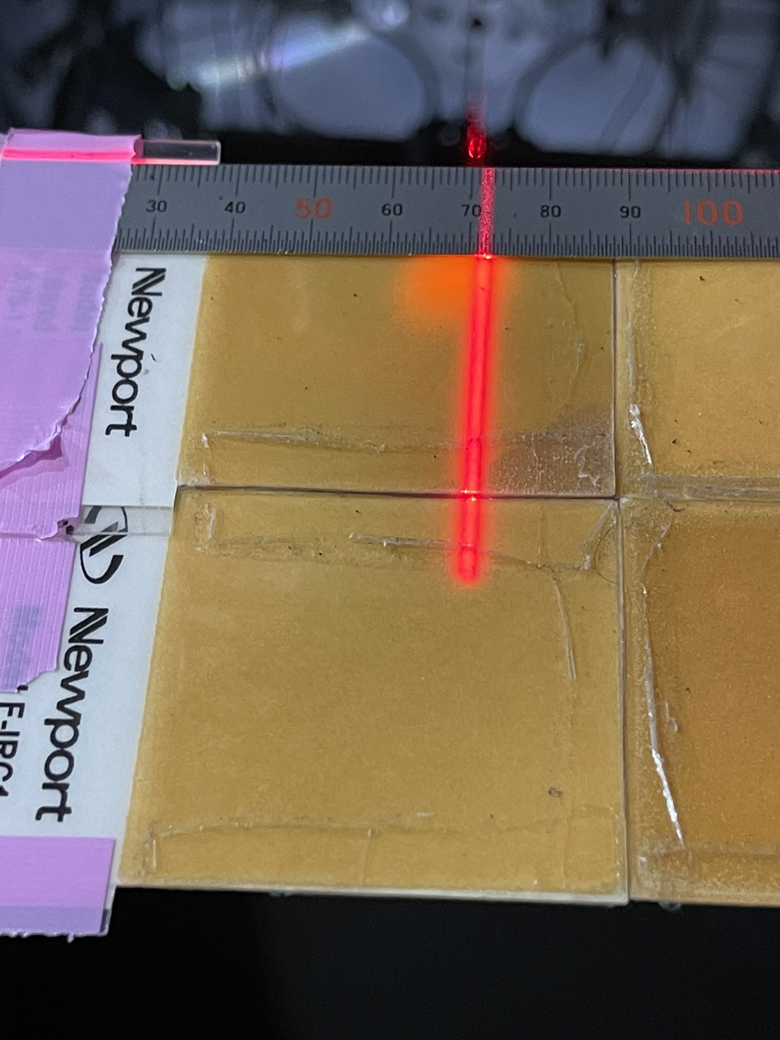
[Hirata, Ushiba-san, Ikeda-san]
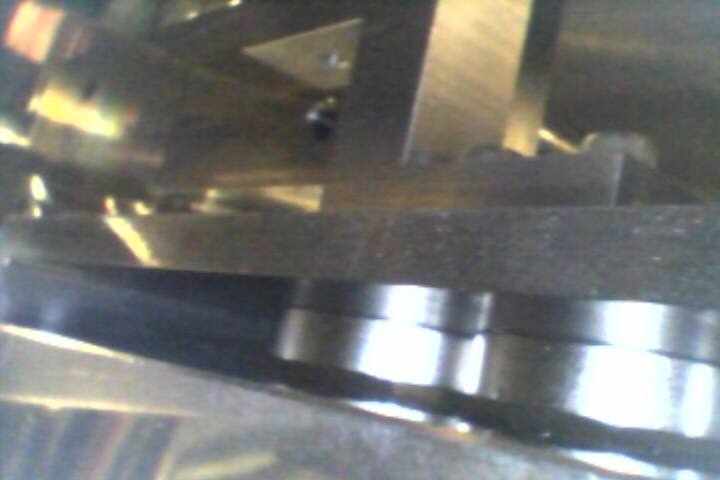
We checked IR beam position around PR2 HR side Mid-size baffle. (How to make the vertical line is same as klog:29282)
It looks that IR beam positon is about 3.5mm +Y side away from the center of aperture.(IR beam center is 68.5mm and aperture center is 72mm on the ruler.)
The readout of the water fluid has recovered.
[YokozaWashimi, Tanaka, Ozaki, Sudo]
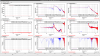
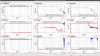
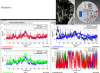
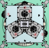
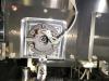
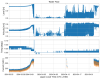
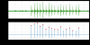
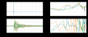
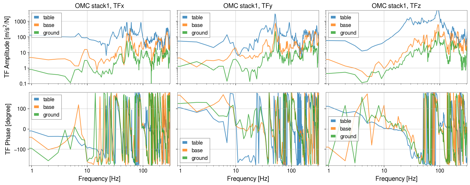
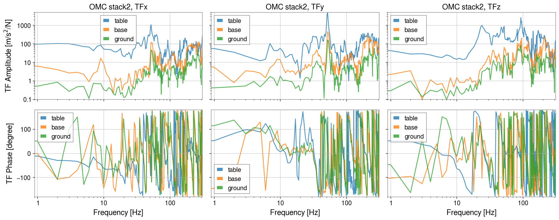
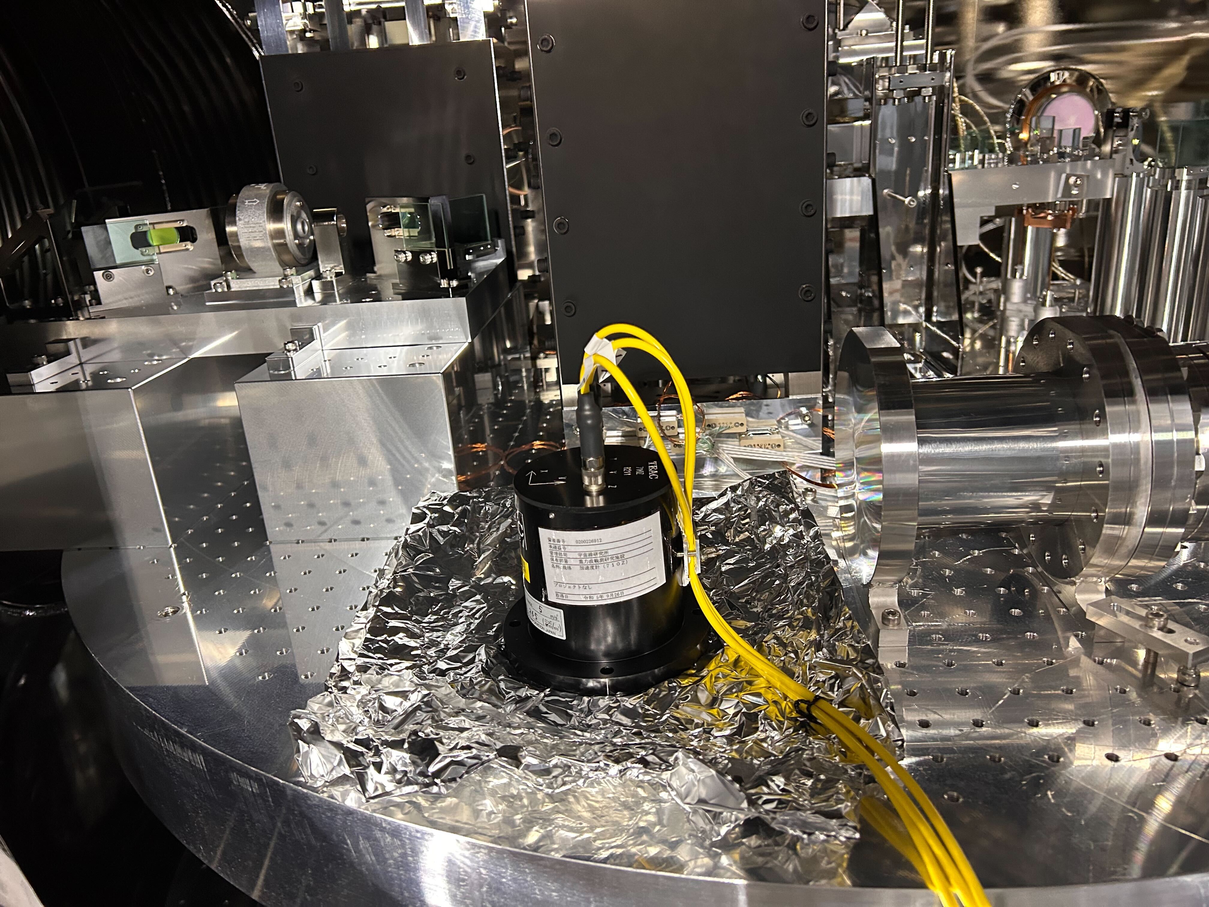
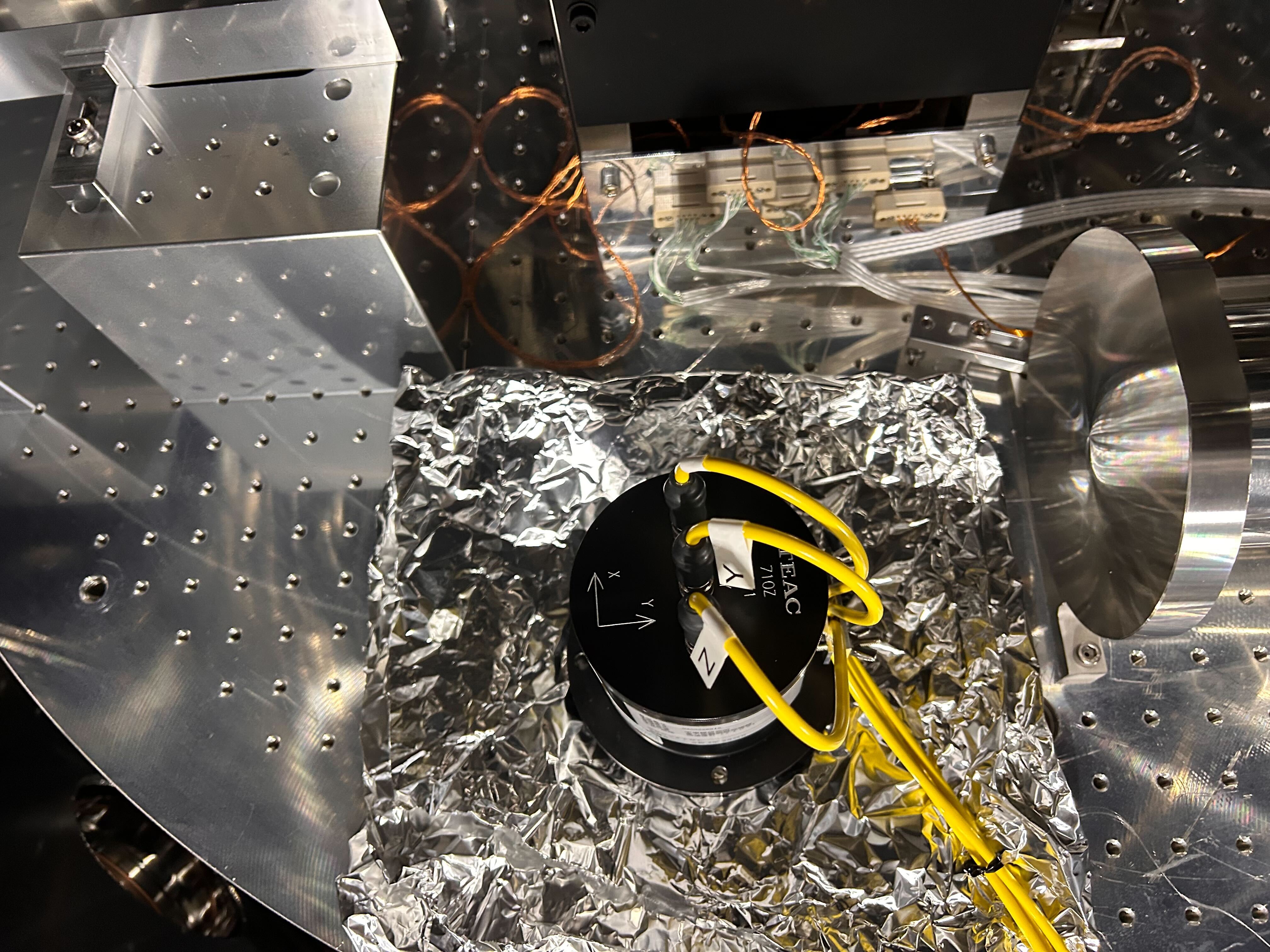
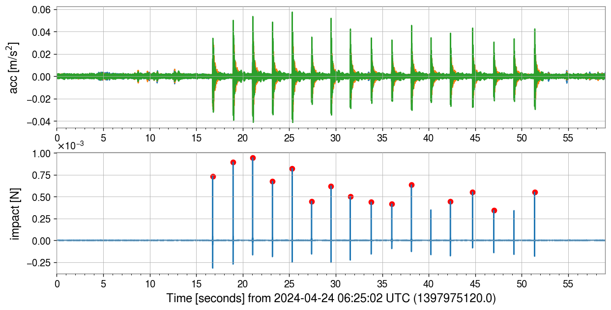
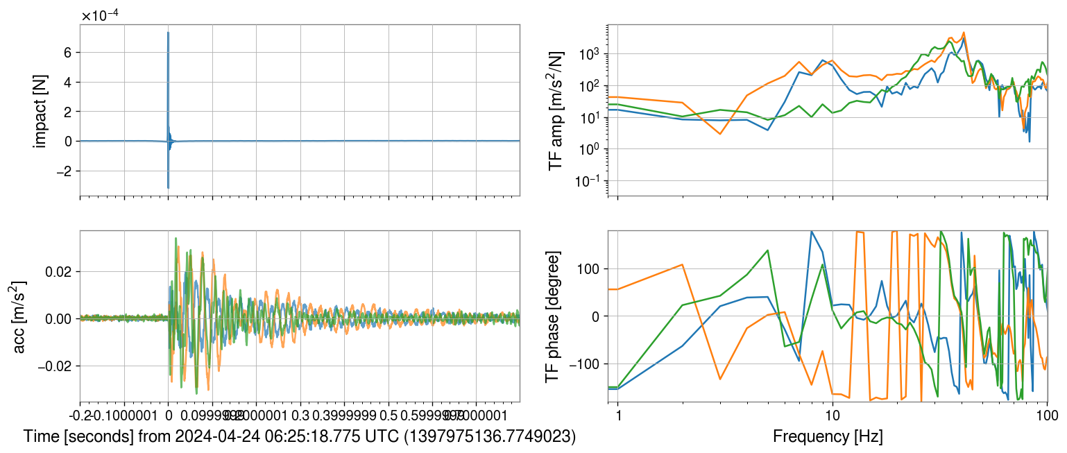
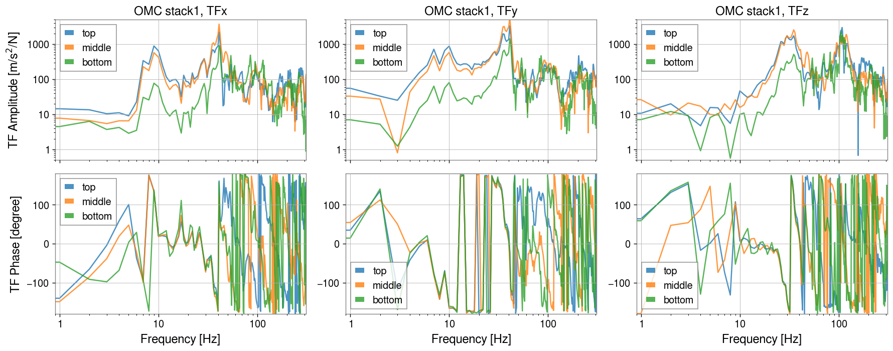
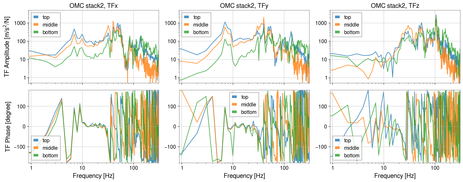
Today we tried to evaluate the seismic isolation of the OMC stacks, using a 3-axial accelerometer (S2315344) and an impact hammer (G1910656).
This is a quick report.
- Locating the ACC on the OMC vac-table (Fig.1, Fig.2)
- Tapping each stack (top, middle, bottom of stack1, stack2) with the impact hammer (direction: Fig.3)
- Picking up each pulse (-0.2/+0.8 sec) and calibrating its transfer functions from impact [N] to acceleration [m/s2] automatically (example: Fig.4, Fig.5)
- Calculating averages of the events (Fig.6, Fig.7)

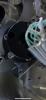
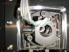
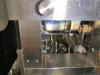
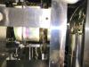
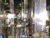
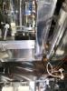
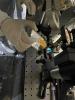
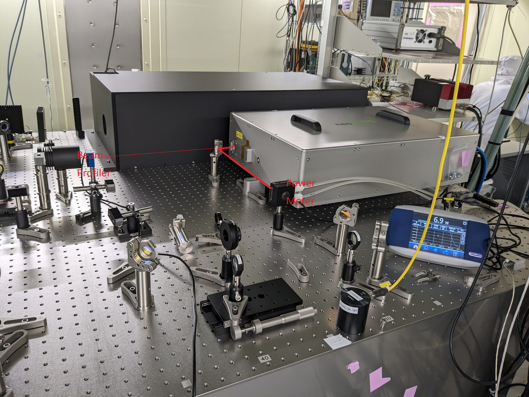
We checked some laser operations. And we set a mirror for beam profile measument later(fig1).

[Hirata, Ushiba]
Abstract:
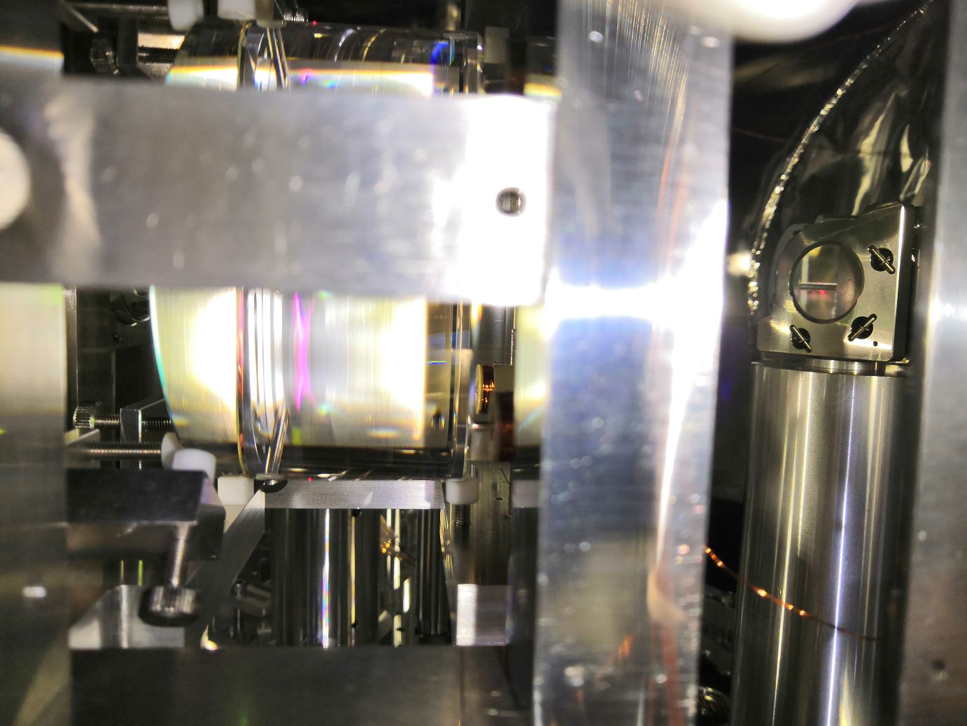
We reconstructed POP forward beam path.
Though beam is still close to the knob of mirror mount just after periscope, the beam doesn't seem clipped.
Now, IR beam hits almost center of the both QPDs when the alignment to PR2 is good.
Detail:
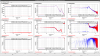
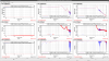
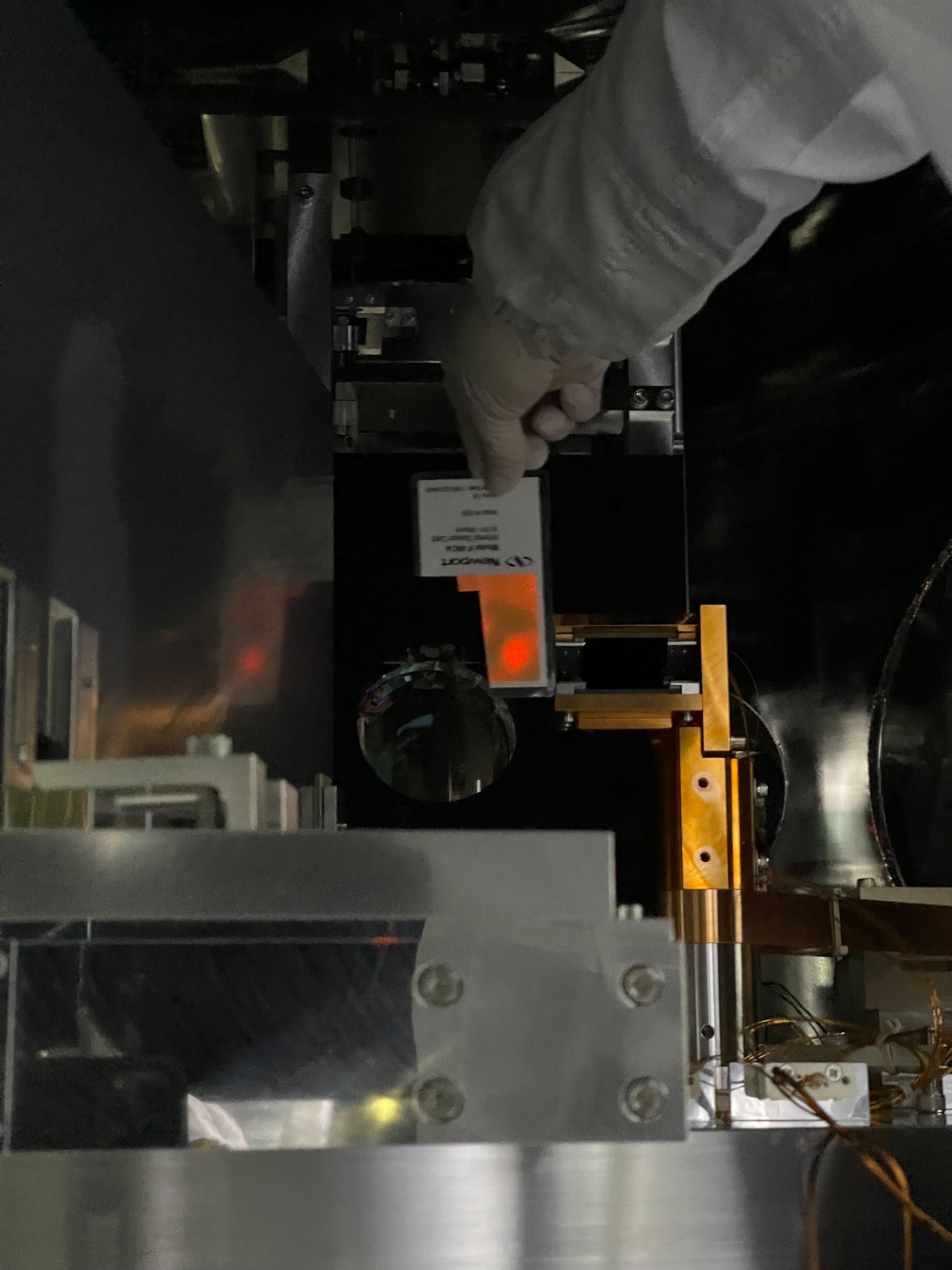
1. Check of beam position at high power beam dump:
First, we requested aLIGNED state for IMMT1, IMMT2, and PRM.
Then, to confirm the good alignment has been kept from yesterday, we checked the beam spot on the PR2 HR target, which is almost center (fig1): good.
After confirming the alignment is good, we checked beam at high power beam dump (fig2).
Beam path seems far enough from the beam dump: also good.
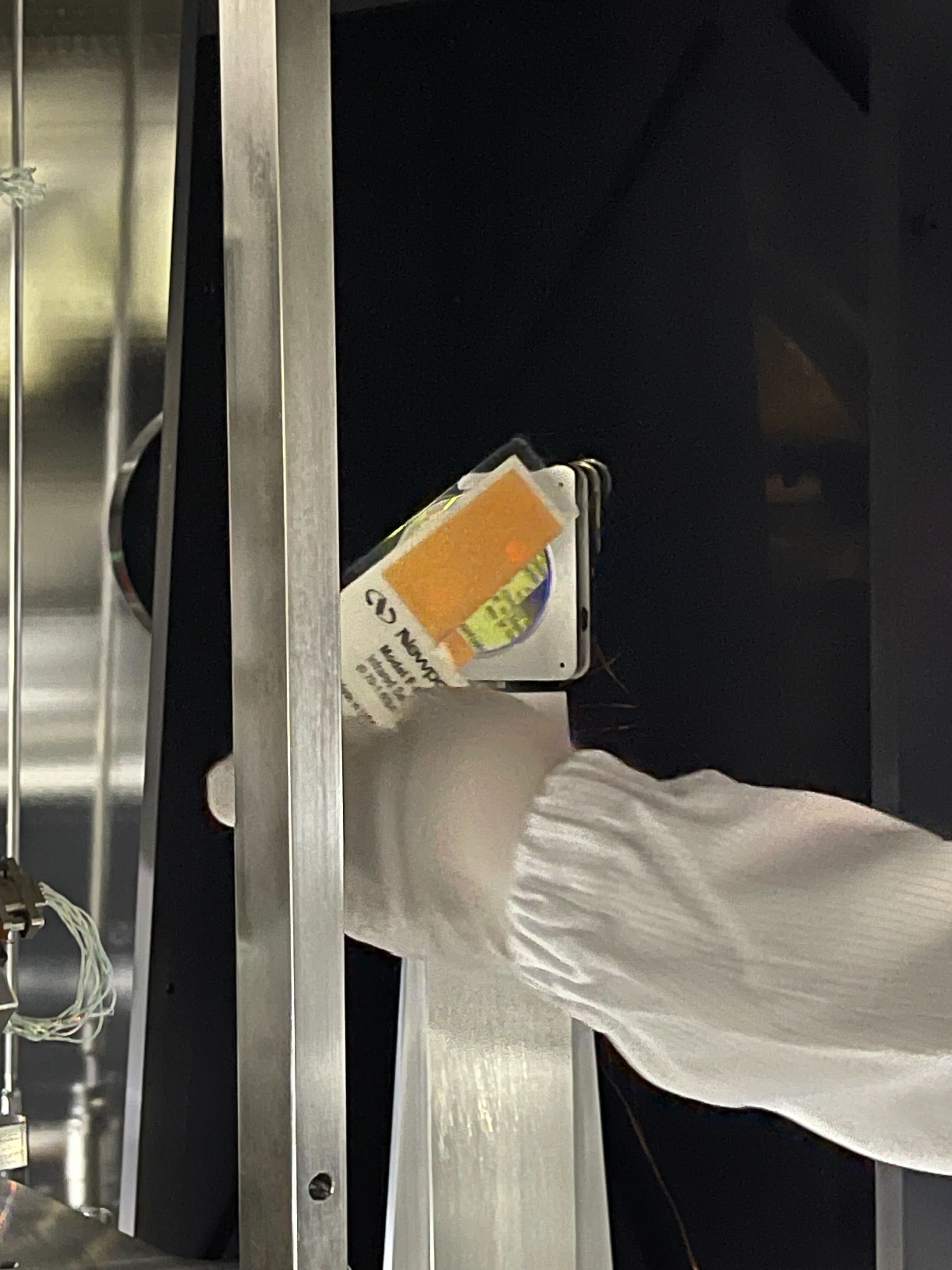
2. Check beam spot on in-vac POM behind PR2:
After confirming the IR alignment to PR2, we checked beam spot on in-vac POM behind PR2 (fig3)
It is hard to say from the picture, but no clip happens at in-vac POM in my eyes.
3. Reconstruction of POP forward beam path:
After confirming beam spot on in-vac POM is not so bad, we started reconstruction of POP forward beam path.
At upper mirror on the periscope, the beam is not center but it seems no clip (fig4), so we keeep it as it is.
Then, we moved upper periscope actuators and hit the beam on the mirror center of lower mirror on the periscope (fig3).
After that, we moved FST1 in JGW-T1909623-v11, because it is hard to avoid clipping without moving the mirror.
Then, we aligned the beam to lower right of the FST1 (fig6) to avoid clipping at the knob of the mirror mount.
Figure 7 shows the current beam spot near the knob, which seems not so bad in my eyes.
After that, we realigned all the downstream and centered the QPDs.
Note:
During the work, on of the actuators of lower mirror mount on the periscope hits the periscope itself and cannot rotate to CW direction (we can rotate it in CCW direction).
So, we cannot move up the beam spot on FST1 without moving periscope mirror upward.
Since I am not familiar with the periscope installed for the POP forward, I didn't lift it up and keep it as it is.
