Reports 1-1 of 1 Clear search Modify search
MIF (General)
yuta.michimura - 10:08 Friday 19 April 2024 (29275) Print this report
First results from BS transmission measurements

[Shimasue, Takano, Michimura]

BS transmission at ~45 deg was measured to be:

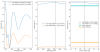
50.8 +/- 0.9 % for s-pol
78.3 +/- 1.6 % for p-pol

They are consistent with the design (see, also, klog 29269 and JGW-T1503347)

What we did:
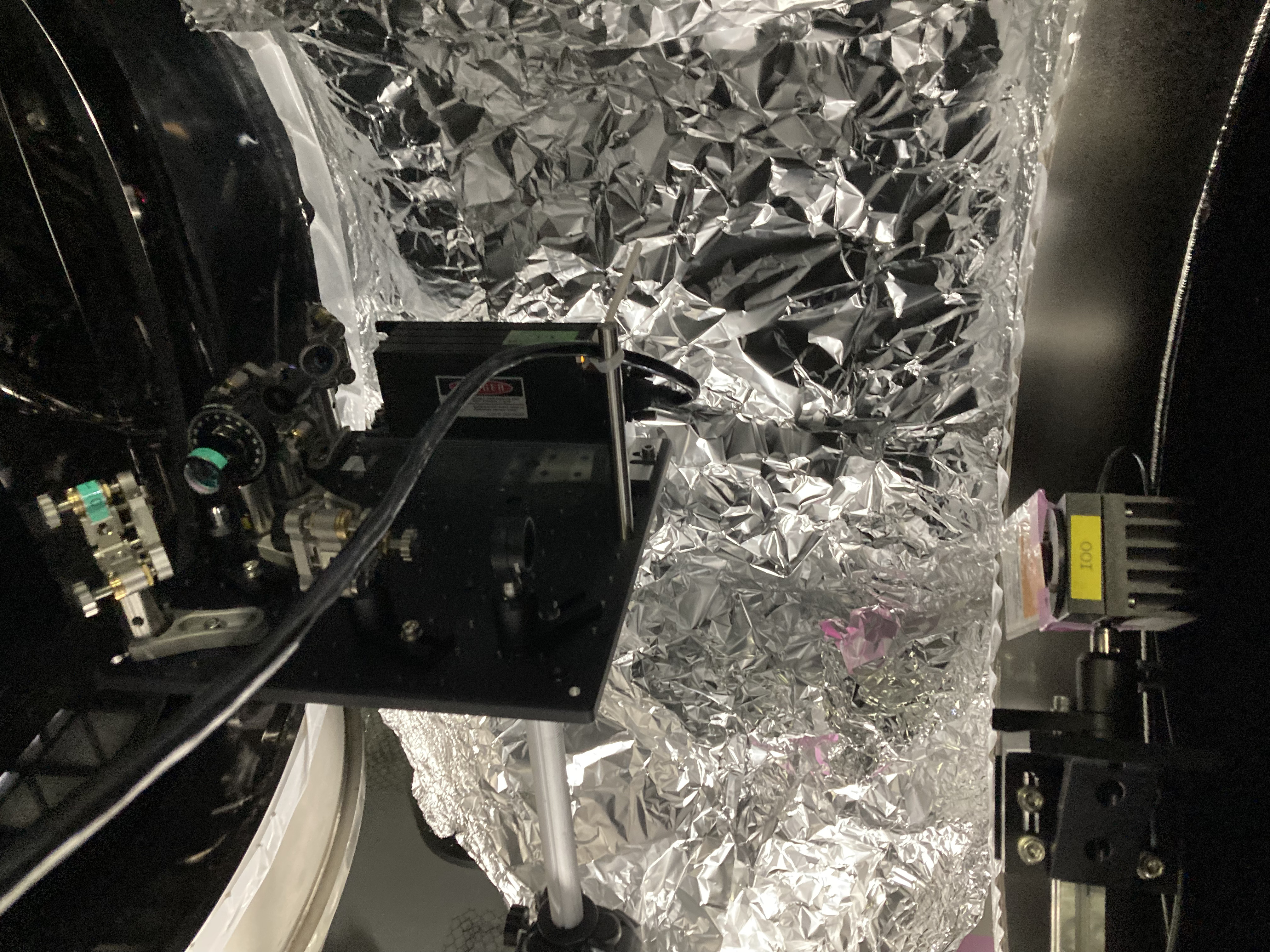
 - Assembled a tripod setup for injecting the probe beam at IMC REFL area. We had a hard time collimating the beam for a few meters with the beam size smaller than the aperture of the power meter (Thorlabs).
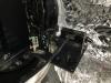
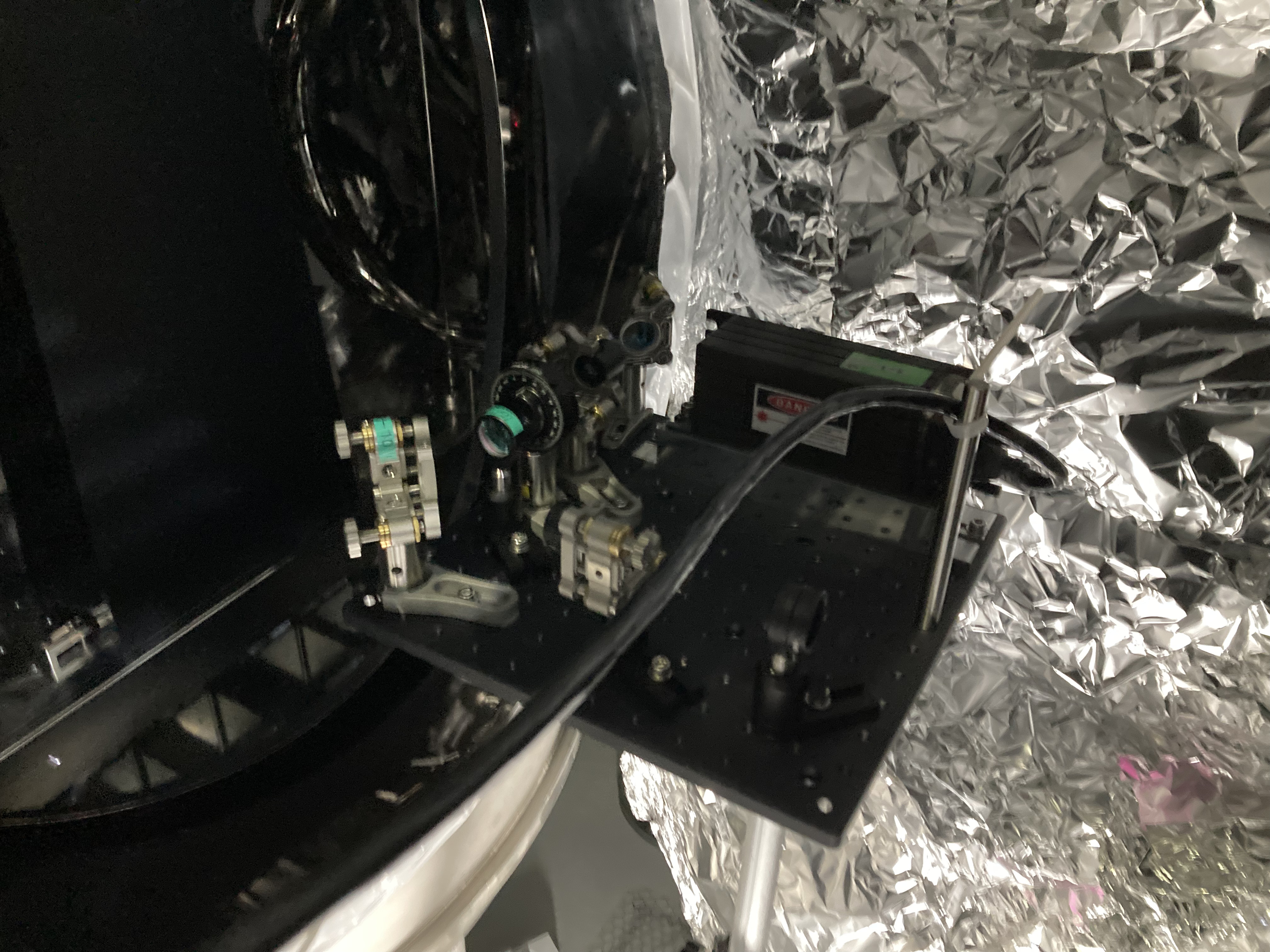
 - The injection bench consists from the laser source -> steering mirror -> Glan laser prism (rotated so that it transmits most of the beam, which was mostly s-pol) -> HWP -> f=-75 mm lens -> steering mirror -> Glan laser prism (rotated to define the polarization of the probe beam) -> f=300 mm lens (Attachment #1)
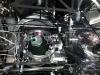
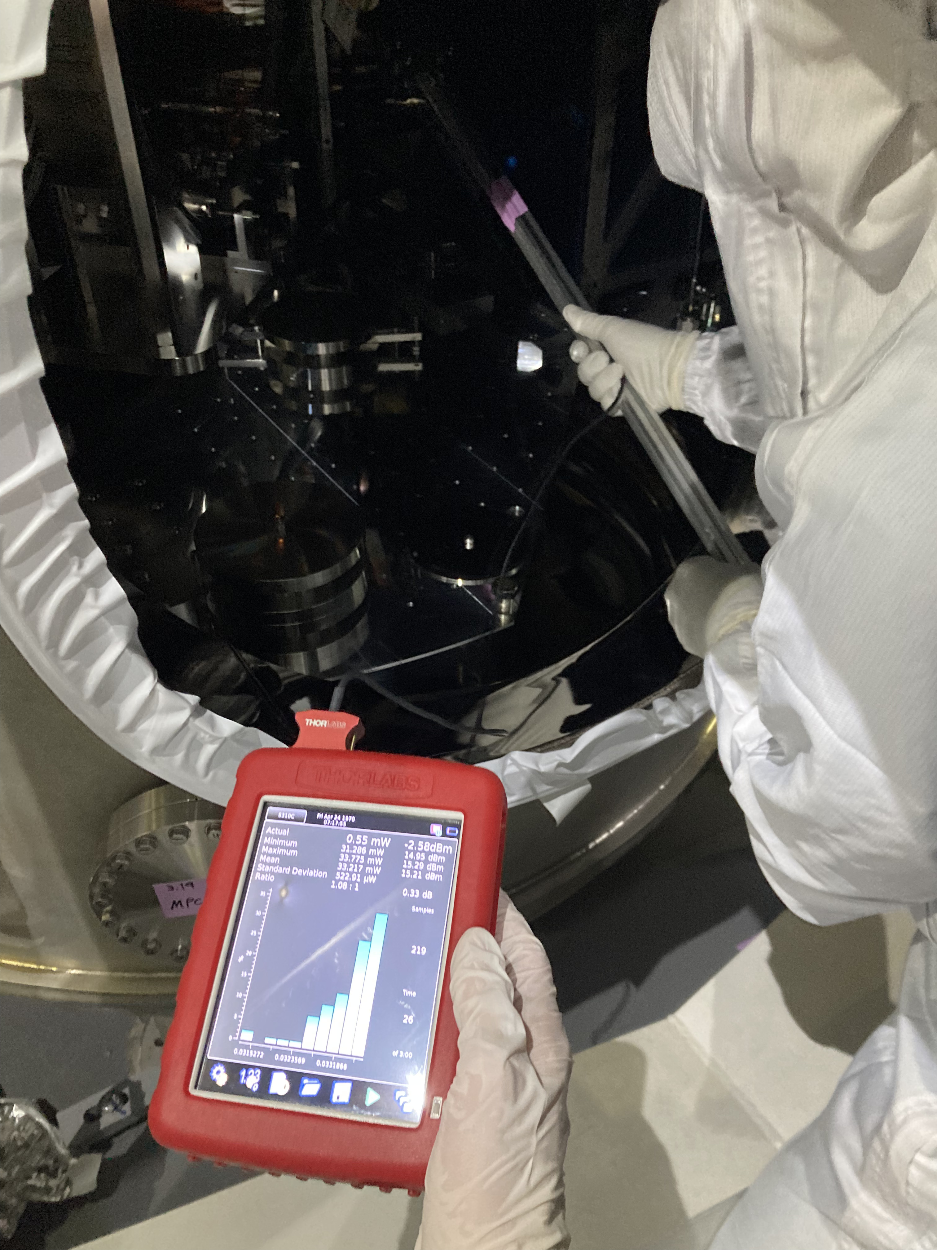
 - Put the power meter head on a stick so that we can stick it inside the BS chamber (Attachment #2) to measure the power of transmitted beam. IR card was also put in front of the power meter head to find the beam.
 - Brought these setup to the BS area, and put the tripod setup for injecting the probe beam between BS and PR2 chambers.
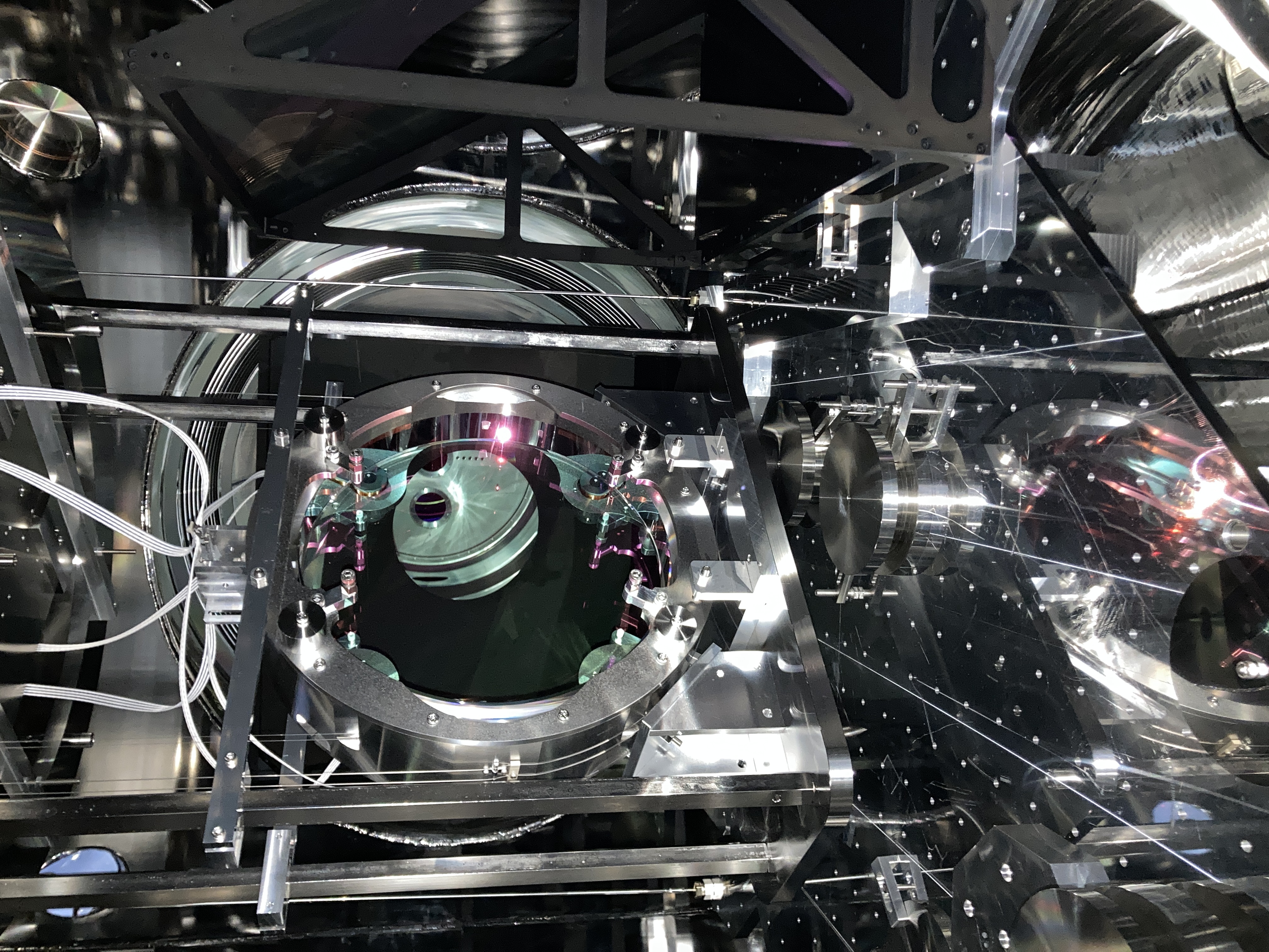
 - The alignment of the incident beam, both in pitch and yaw was tuned by eye by centering the beam on BS.
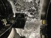
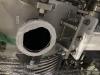
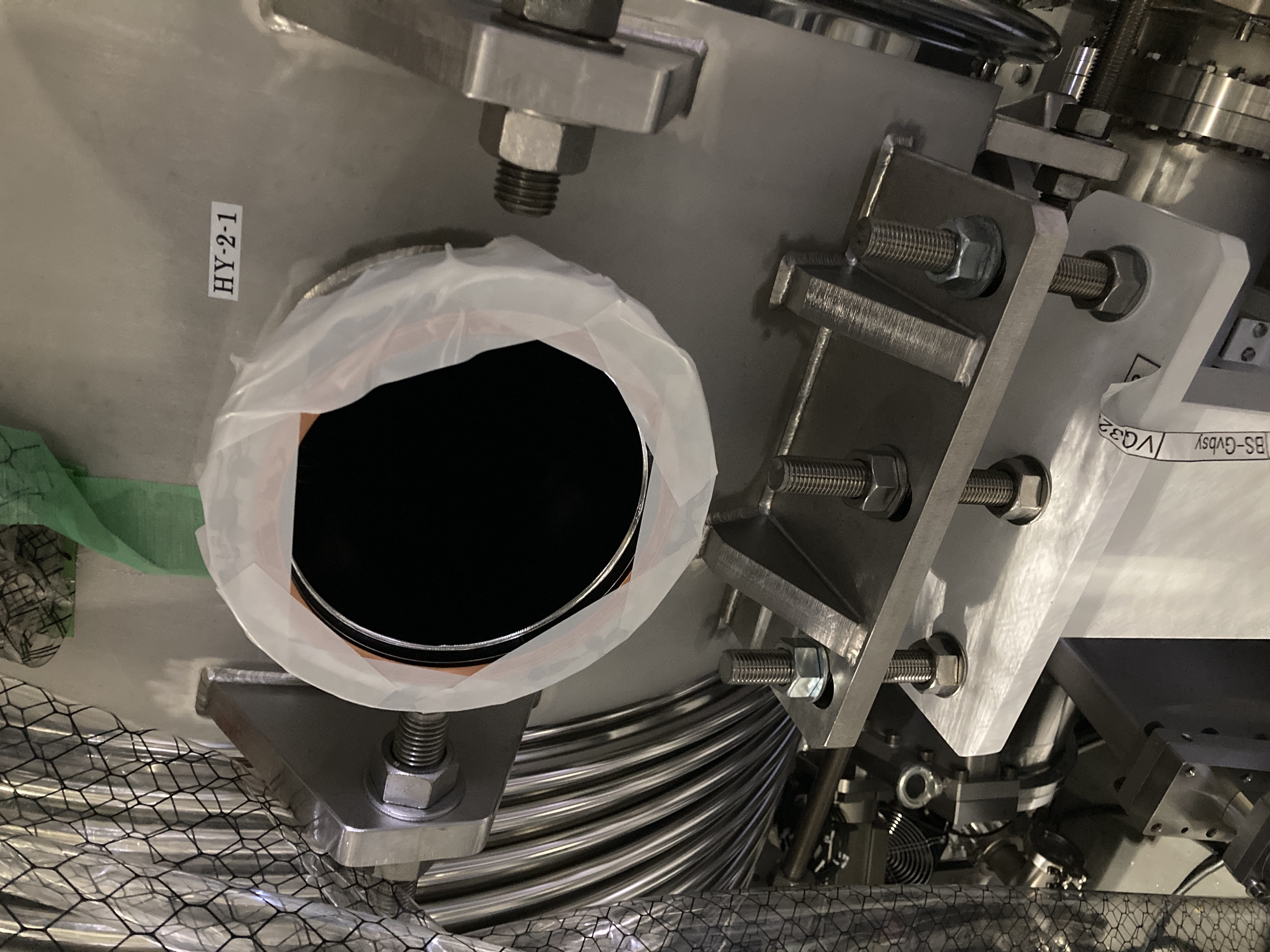
 - Measured the incident power at the injection bench, after the last lens (Attachment #3), and the transmitted power at the back of BS (Attachment #4) by holding the power meter on stick by hand. The stick was rested on a ground and/or some vacuum structures so that the head will be stable.
 - The polarization of the probe beam was tuned by eye by rotating the second Glan laser prism (OptoSigma GLPB2-10-25.9SN-7/30). When the white line is vertical, it is s-pol and when horizontal, it is p-pol. The HWP was tuned to maximize the probe beam power.

Results:
 - The table below summarizes the results

polarization incident power BS transmitted power
s-pol 44.98 +/- 0.75 mW 22.87 +/- 0.18 mW
p-pol 42.44 +/- 0.54 mW 33.21 +/- 0.52 mW

 - By calculating T = (BS transmitted power) / (incident power), BS transmission was estimated.

Discussions:
 - The measured values are consistent with the coating design shown in  JGW-T1503347.
 - The incident angle was tuned within a few mrad (beam centering error of a few cm over injection bench to BS distance of 3.3 m).
 - Mis-tuning of the incident angle by a few mrad can be converted into laser wavelength mis-tuning of a few 0.1 %.
 - According to the coating design in JGW-T1503347, HR reflectivity and AR reflectivity does not depend very much on laser wavelength, and probably we will be still be limited by the uncertanties in the power measurement, even if we tune the incident angle more carefully.

Next steps:
 - Measure reflectivity by sticking a power meter from the ICF203 flange between BS and ITMY.
 - Re-do the measurements after aligning ITMs. Use ITM reflection to more carefully align the probe beam to the BS so that the incident angle will be the same with the main beam. (But this is probably uncesessary considering the uncertainties of the power measurement)
 - Estimate systematic uncertainties from the polarization orientation of the incident beam, the incident angle etc.

Images attached to this report
Comments to this report:
yuta.michimura - 15:51 Friday 19 April 2024 (29279) Print this report

[Shimasue, Takano, Michimura]

BS transmission and reflectivity were measured to be:

Ts=51.9 +/- 0.2 for s-pol
Rs=47.7 +/- 0.2 for s-pol
Tp=77.7 +/- 0.6 for p-pol
Rp=21.8 +/- 0.2 for p-pol

BS transmission for s-pol is a bit too high, which might be because BS is not aligned (it is now in SAFE state).
We might need to measure them again once BS and ITMs are aligned.

What we did:
 - Followed the procedure in klog 29275 for measuring the BS transmission.
 - For BS reflection, we opened an ICF203 flange labeled HY-2-1 (Attachment #1) so that we can stick the power meter (Thorlabs S310C) from the hole (Attachment #2).

Results:
 - The table below summarizes the results

polarization incident power BS transmitted power BS reflected power
s-pol 38.224 +/- 0.061 mW 19.832 +/- 0.087 mW 18.248 +/- 0.088 mW
p-pol 36.931 +/- 0.067 mW 28.696 +/- 0.211 mW 8.062 +/- 0.062 mW


 - By calculating T = (BS transmitted power) / (incident power) and R = (BS reflected power) / (incident power), transmission and reflectivity were estimated.

Discussions:
 - We noticed that the beam reflected by BS is not going through the viewport at the gate valve. We then realized that BS is not in ALIGNED state, but in SAFE state.
 - This means that the incident angle to the BS might be off by 50 mrad (~15 cm over 3.3 m distance).
 - The measurent tells that AR reflectivity is small enough compared with the measurement uncertainties.

Next steps:
 - Estimate the effect of incident angle from the wavelength dependence from the design.
 - Re-do the measurements with BS and ITMs aligned.

Images attached to this comment
yuta.michimura - 22:55 Friday 19 April 2024 (29284) Print this report

Systematic uncertainties on BS transmission and reflectivity measurements were estimated.
Updated results are:

Ts=51.9 +/- 0.2 (stat.) +/- 0.2 (sys.) % for s-pol
Rs=47.7 +/- 0.2 (stat.) +/- 0.2 (sys.) % for s-pol
Tp=77.7 +/- 0.6 (stat.) +/- 0.2 (sys.) % for p-pol
Rp=21.8 +/- 0.2 (stat.) +/- 0.2 (sys.) % for p-pol

Here, uncertainties from the incident angle and the polarization angle are considered.
It seems that they are not responsible for Rs being to low and Rp being too high, compared with the design.

Incident angle error:
 - BS and the incident beam was not aligned perfectly to have the incident angle of 45 deg. BS was in SAFE state.
 - BS reflected beam was not going though the viewport at the gate valve between BS and ITMY. The beam spot was off by ~15 cm over 3.3 m distance. From this, we have estimated that the incident angle error is about 50 mrad (3 deg).
 - Left panel of Attachment #1 is the reflectivity from the coating design, extracted from JGW-T1503347. The middle panel is the zoomed plot around 1064 nm.
 - From this, we can estimate the incident angle dependence as follows.
 - Reflectivity can be written as

R = R0 + dR/dtheta * dtheta

where theta = theta_in/n_eff is the incident angle inside the coating with an refractive index of n_eff (we used n_eff=1.7).
Slight change in theta_in introduces effective coating thickness change, which is equivalent to the laser wavelength change of

dlambda = lambda/cos(theta+dtheta) - lambda/cos(theta)
 = lambda/cos^2(theta)*sin(theta)*dtheta
 
 Therefore,

dR/dtheta_in = dR/dlambda*dlambda/dtheta*dtheta/dtheta_in
 = dR/dlambda*lambda*1/cos^2(theta)*sin(theta)*1/n_eff

 - From the coating design, dR/dlambda is -7e-3 %/nm for s-pol and -3e-4 %/nm for p-pol.
 - From the equations above, this gives dR/dtheta is -4e-2 %/deg for s-pol and -2e-3 %/deg for p-pol (Right panel of Attachment #1).
 - 50 mrad gives dR of 0.1% for s-pol and 0.006% for p-pol.

Polarization angle error:
 - When the polarization angle from s-pol is phi, the measured R will be

R = Rs*cos(phi)**2 + Rp*sin(phi)**2

 - If phi had an error of 5 deg, dR will be 0.2% for s-pol and p-pol.
 - It is hard to explain Rs being too low by ~2%, just from the polarization angle error.

Discussions:
 - Combined systematic uncertainties are 0.2% for all.
 - Rs seems to be too low and Rp seems to be too high, compared with the design.
 - The other source of error could be from the offset of the power measurements from the ambient light.
 - We could also try aligning the polarization angle by maximizing (for s-pol) or minimizing (for p-pol) BS transmission.
 

Images attached to this comment
Search Help
×

Warning

×