R. Kozu, Y. Fujii,
log on Dec. 1st 2018
= SR3 =
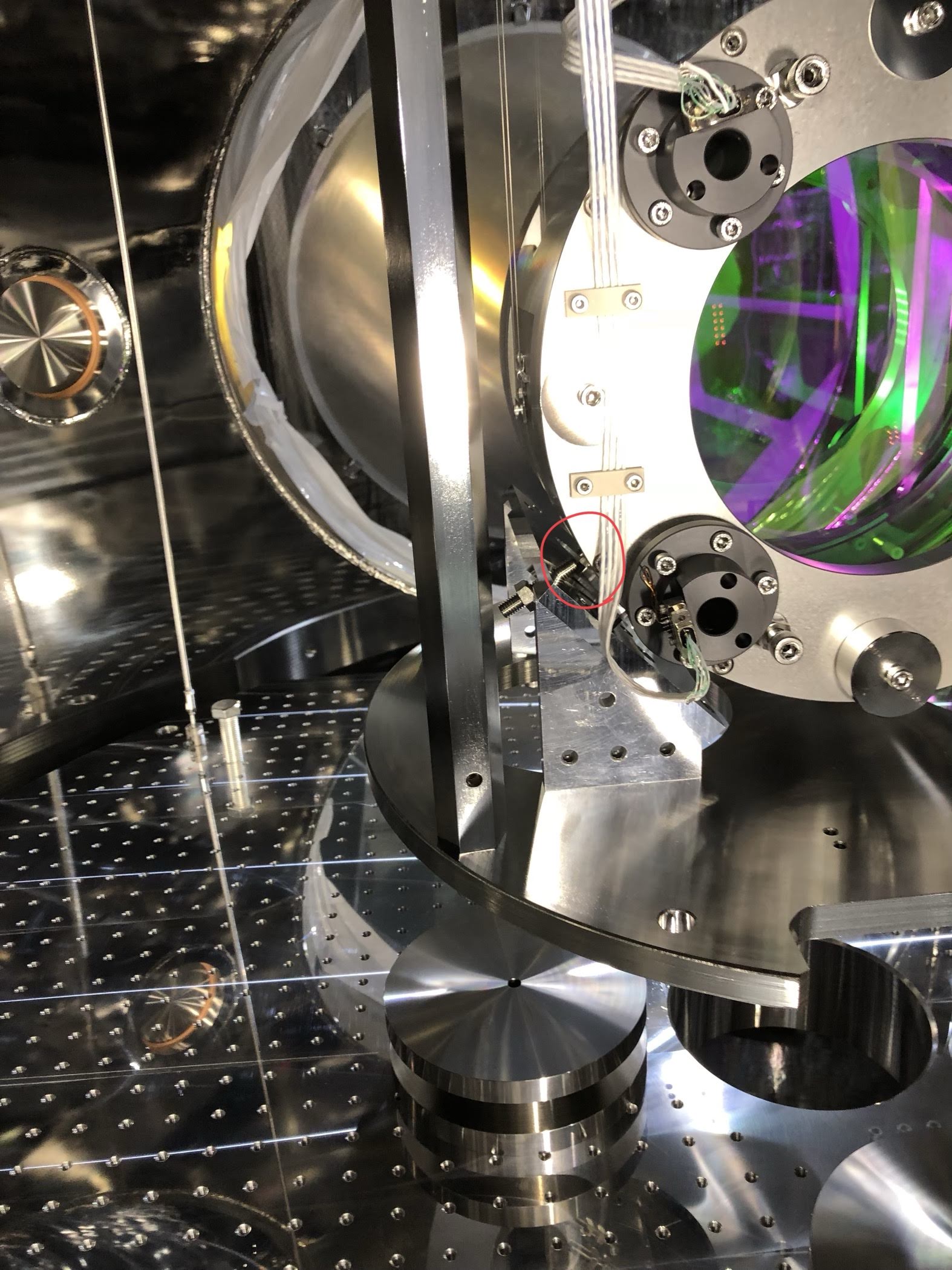
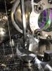
In the measurement campaign by Kozu-kun, we found that the RM was sitting on the EQ frame as Fig1 shows, and this bothered his measurement.
== Background ==
- Kozu-kun found that relatively large drift was occurred in every sensor on SR3 in the midnight on Nov. 30th, Friday.
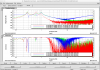
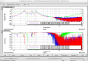
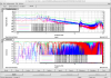
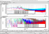
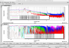
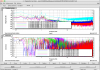
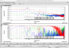
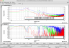
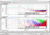
- during the re-aligning work of the oplev spot on the QPD with IM actuators, he found that he could not push the Optic in Yaw by actuating IM coils, and the optic's free-swinging spectrum in Yaw was much smaller than the spectrum in Pitch in the range of about 0.1 to 1 Hz.
- From this, first, we suspected that IM etc was touching to smewhere and wanted to compenstaed with vertical stepping motors though, we found that the stepping motor drivers for GAS was not in online and could not adjust the height remotely.
== What we saw/did in the tunnel ==
1. we found the SR3-GAS stepping motor drivers were not powered on, and we thus turned on it.
2. we found that the RM was sitting on the EQ frame at the fixing screw as Fig1 shows.
3. Since I was believing that everything was fine before the drift on Nov. 30th midnight, and since the position of the F0/F1/BF-keystones became lower than before the drift a bit (i.e., GAS drift was the cause of this issue), I compensated the gap by GAS-LVDTs. However the issue was not solved.
It seemed that this issue was not occurred by the drift on this Friday but before it.
** from here, I started to do a first aid **
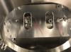
4. I released the RM from the EQ-stopper-screw by adjusting the screws, then after this release, I found the RM was shifted in +L, and +T direction relatively largely and the RM-TM stopper screws hit slightly to the EQ-frame this time like in Fig2.
5. we found that all the LVDTs on IP was at off-centered position. Actually the dc-control target was set a position which was off from the center by about 3 or 4mm in L/T, 3 urad on Y. I could not guess the idea.. and I decided to compensate this offset.
6. Even though I was guessing this might be caused by tilted IP stage (since it seemed that nothing was touching to the payload), here I decided to use stepping motors on IP to save time on that day.
7. Since we did not have STM driver for IP-sliders as reported in klog#7190, I borrowed one STM driver for SRM-IP, and moved the IP-stage in -L, -T direction as much as possible.
By inputting the following steps, the RM-TM stopper screws were de-touched from the EQ-frame as Fig2 shows, though it was shifted in +L, +Y yet:
- position A: -143148
- position B: 165148
- position C: ~165000
We used most of the STM range for this work in the end.
9. After this work, we found that the OpLev beam did not hit to the steering mirror anymore.
10. Since we failed to adjust the beam spot position by tilting the optic pitch with IM-coils (actually the spot did not move in Pitch at all), we suspected some of the RM-TM screws was touching to the TM. Then we loosened the TM-RM stopper screws in some extent.
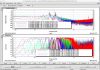
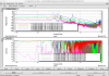
11. We then found that OpLev spot started to oscillate in Yaw but not much in Pit. We also found that the IM-V-OSEMs started to oscillate with higher frequency (just observed in time series). I was not so sure why this was happening yet. This issue should be investigated.
== For next ==
Still, We are not sure why the drift on Nov. 30th happened though, we have to check the suspension condition:
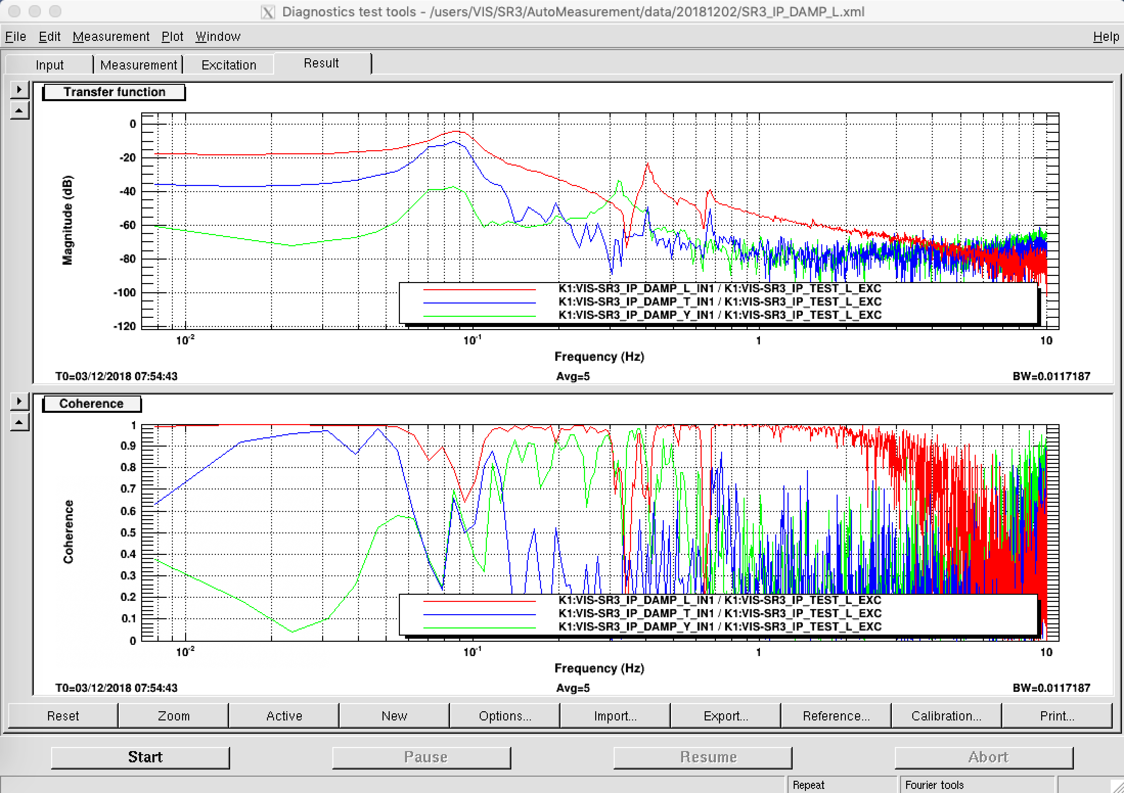
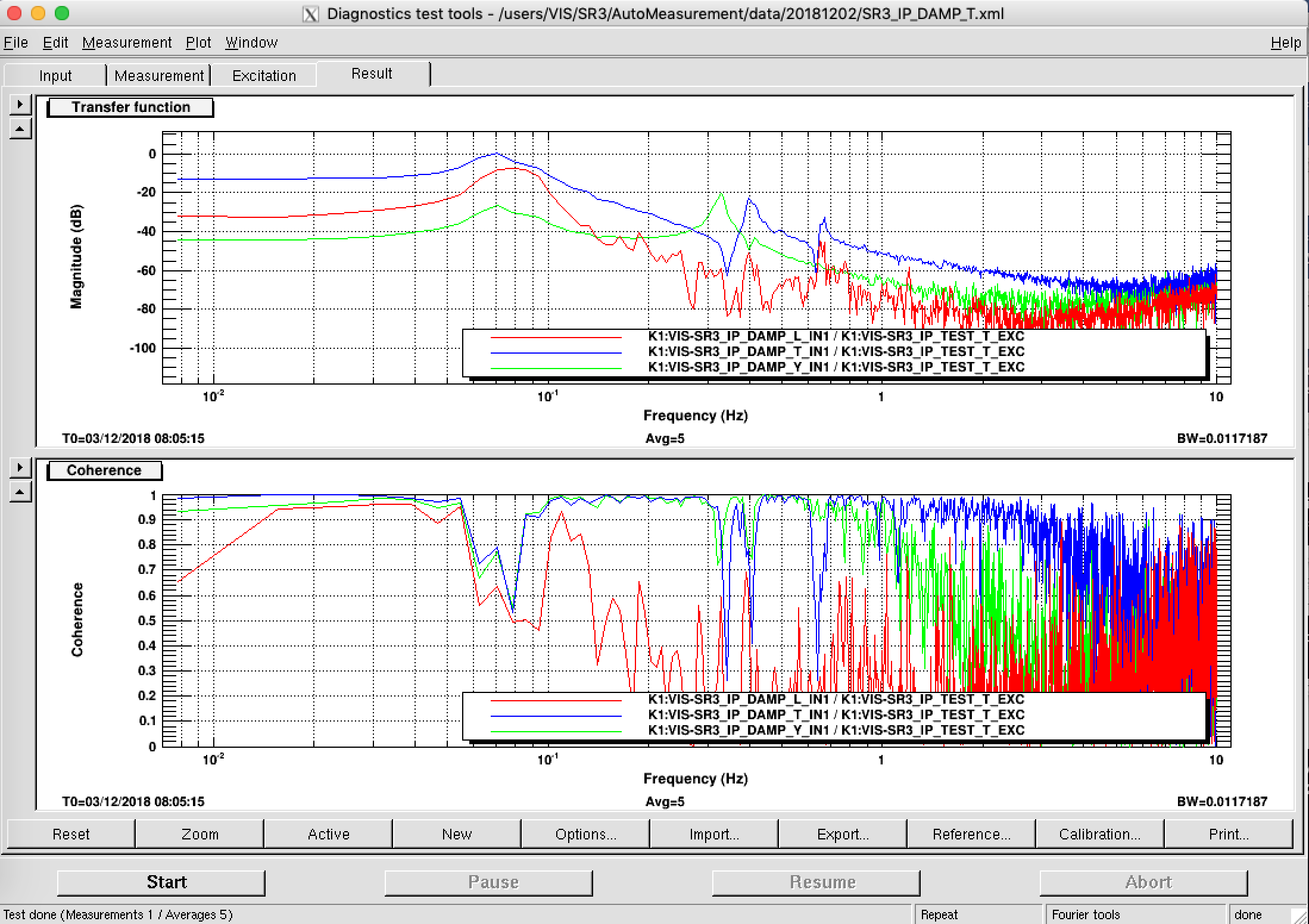
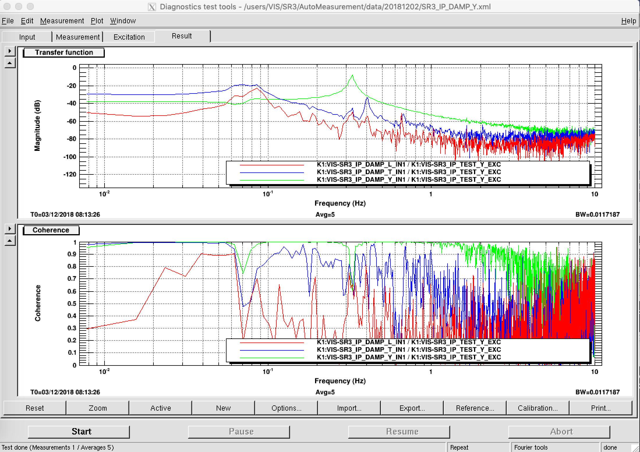
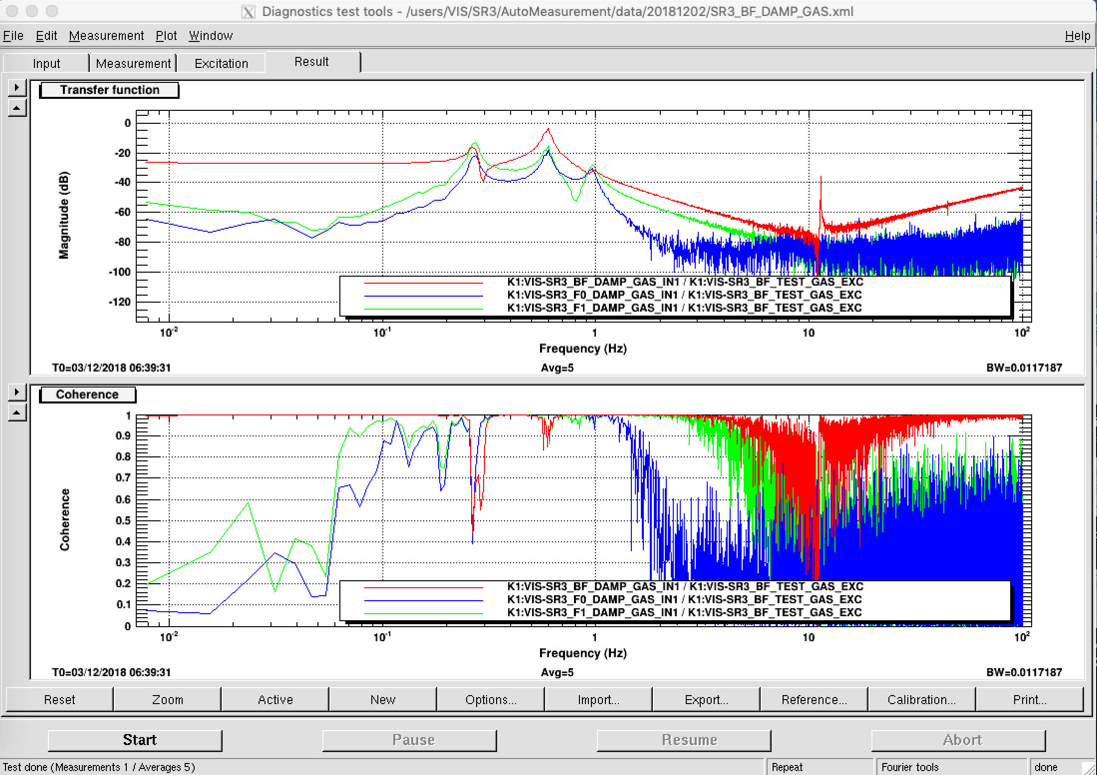
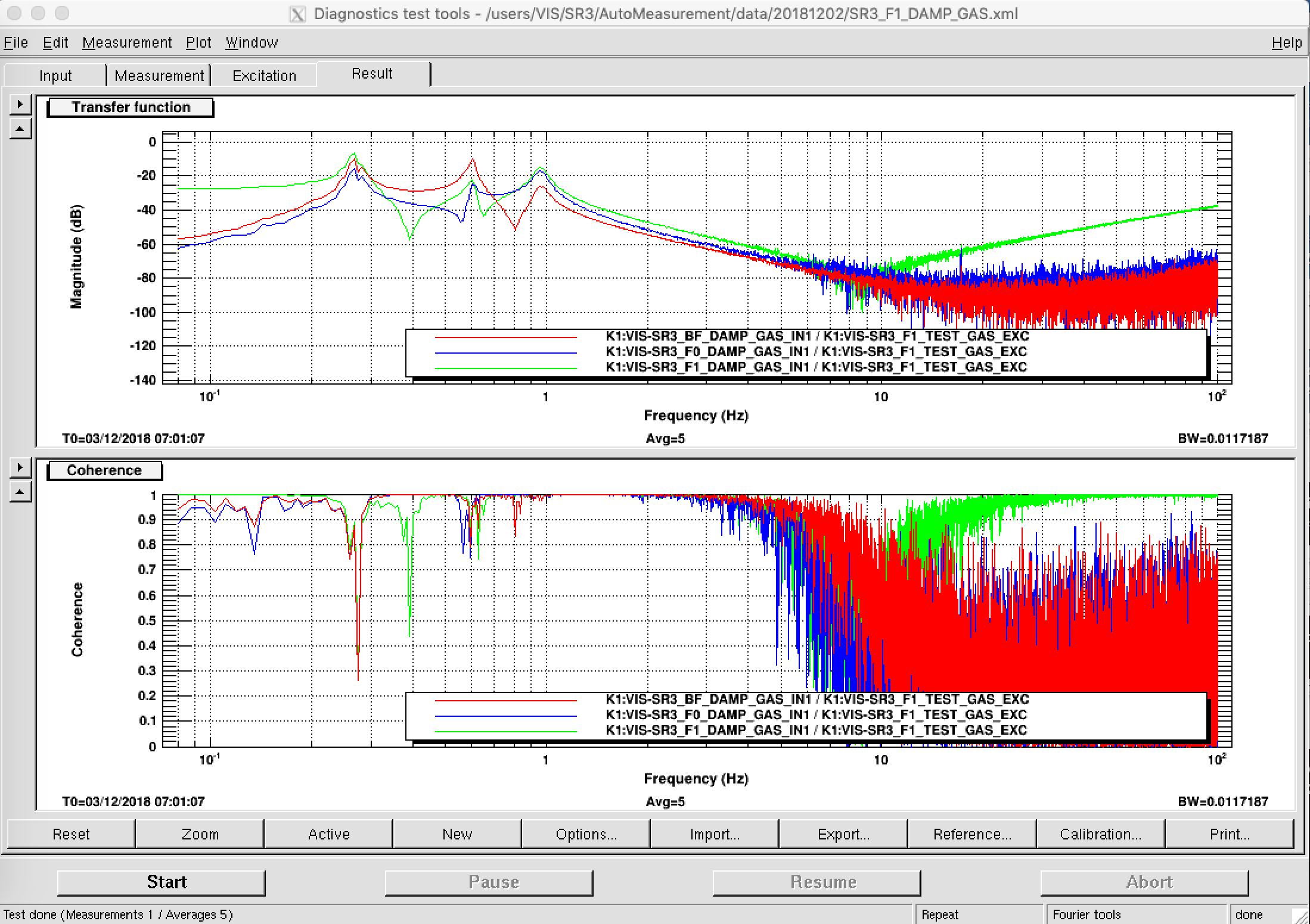
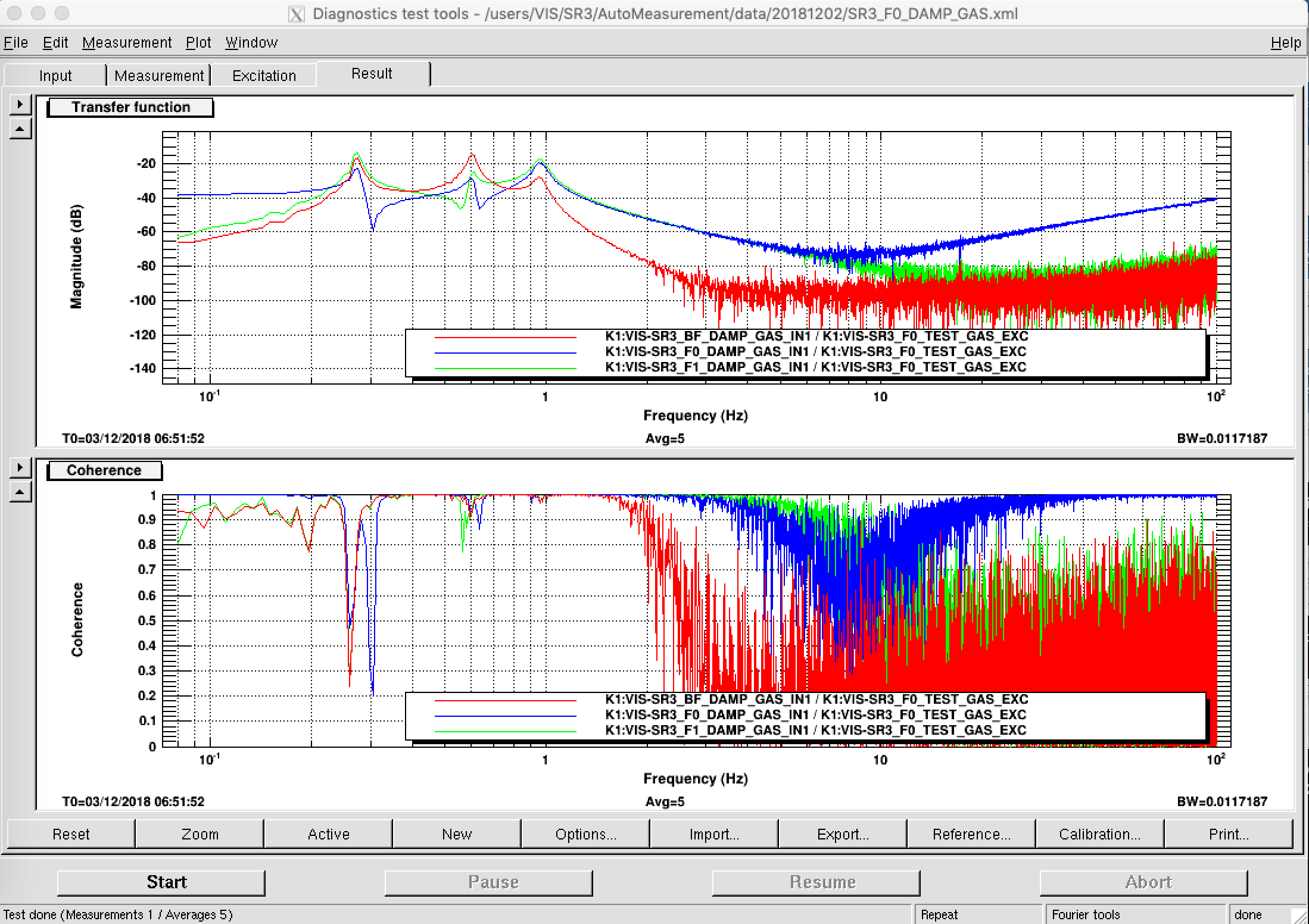
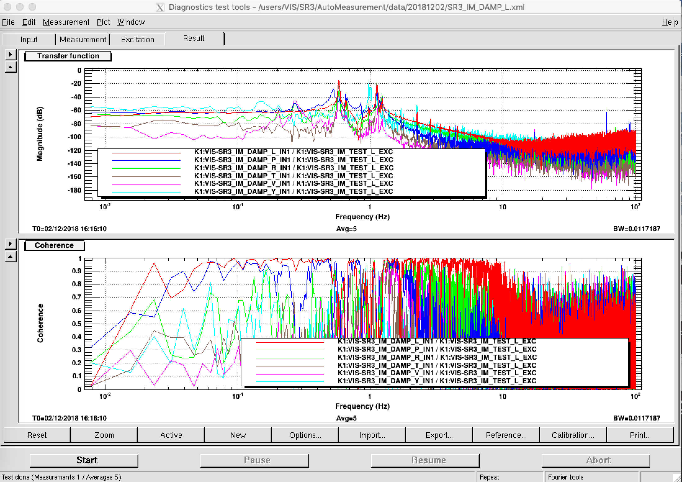
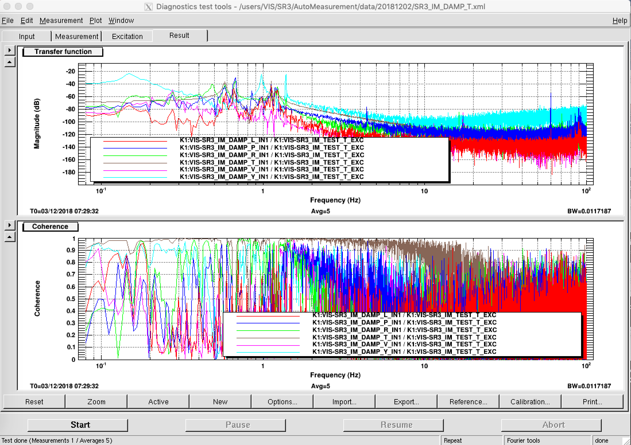
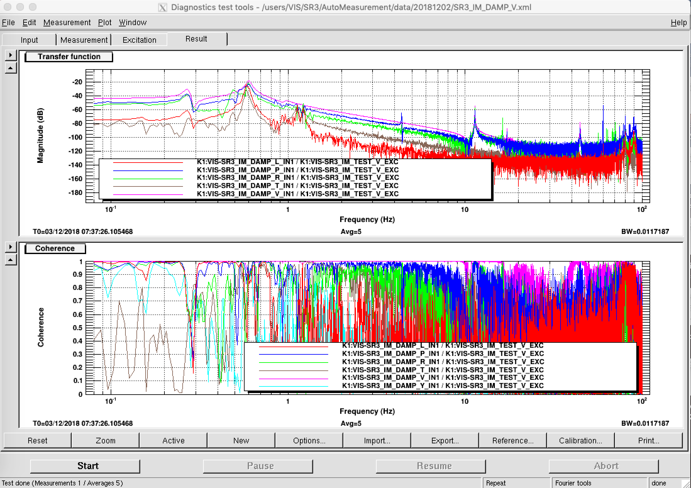
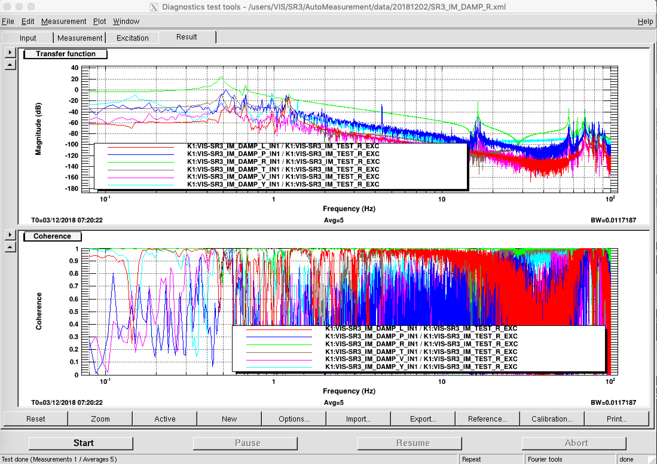
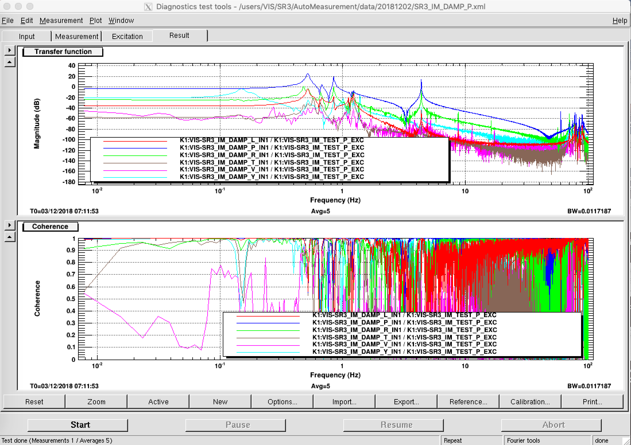
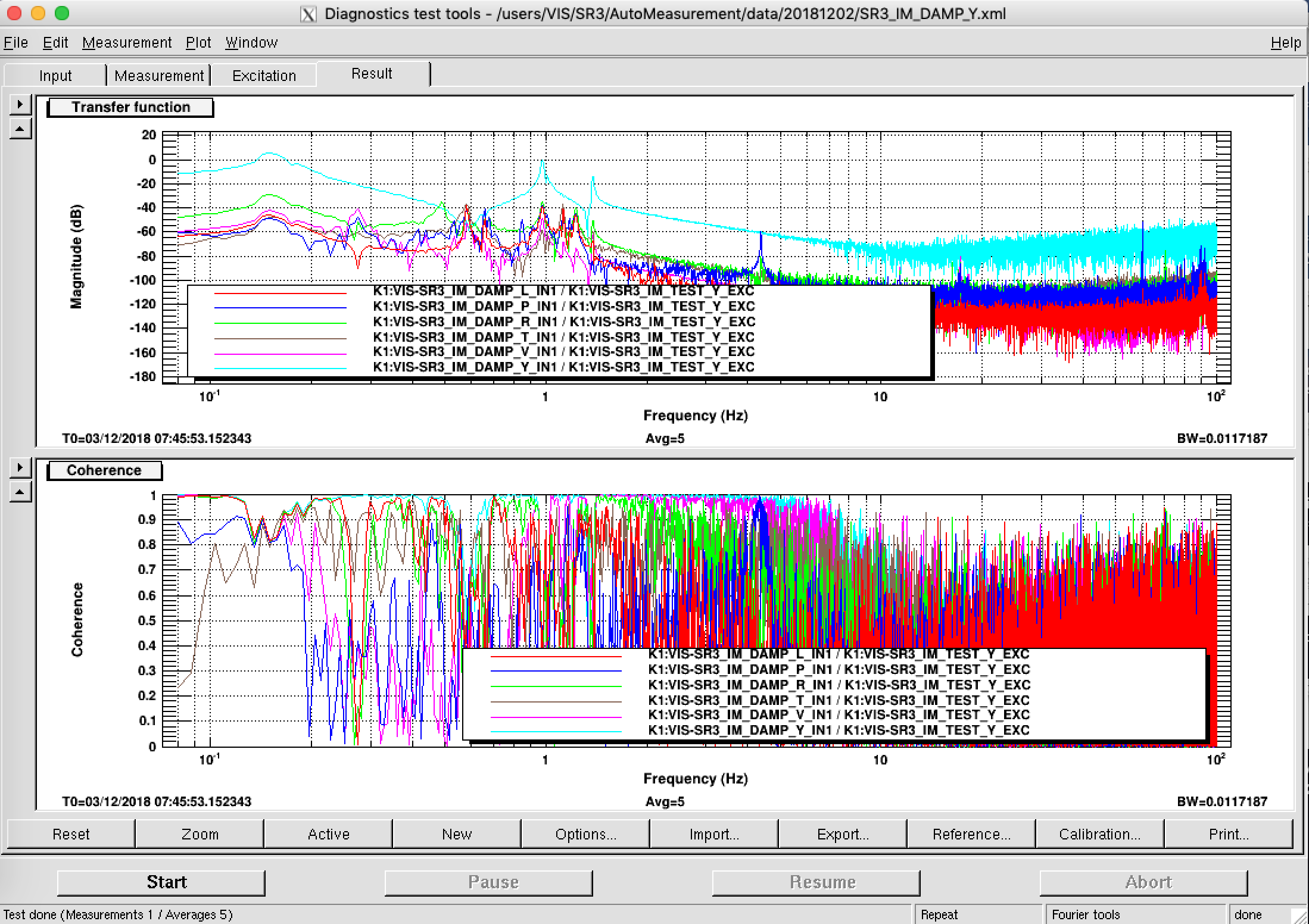
1. Check the SR3 TFs in all the measurable DoFs and check if nothing is touching to the suspension.
2. Inspect the IP condition, and do the initial alignment mechanically.
3. Return the IP-STMs to the initial position, and return the STM driver to SRM.
4. Check the payload condition again by TFs and by eyes.
5. Re-align the OpLev system (I think we will want to ask advice of AOS group again. Please let us have your help in that case..)
6. Check the conditions of all the SR suspensions.
The photos are available from:
https://photos.app.goo.gl/X9BrnXM1DmeWiYFV8
== Notes ==
1. I apologize but I did not return the borrowed STM driver to the SRM rack inside the clean booth.
2. I found the setting of STM driver were partly wrong and firstly it did not work properly even though the driver was in online. I revised this and the re-configured driver was used for this business. (*)
3. We tried to adjust the IM tilt by picomotors in IM though, one cable was missed yesterday somehow, and we could not conduct the adjustment.
(*) This does *not* mean IP-address change or like that, but just network/communication type was changed, and thus this motor driver is used for SRM as it is.
Fig1/Fig2

EVEN YOU, SR3!
We have to install dc-control for IPs and GASs and have to monitor the correction signals soon!
WE DO STOP WHACK-A-MOLE ANYMORE!


