[Okutomi, Shoda, Hasegawa, Kataoka, Ushiba, Fujisawa, Kagawa, Furuhata, Uchiyama, Akutsu, Kokeyama, Michimura]
The main interferometer beam reached EXA.
What we did:
1. Aligned the beam to the GV window between IXA and Yarm by adjusting the PR3 alignment. This was done by looking at the GV window using an IR viewer.
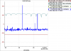
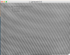
2. At this point we could see the flashing signal with DC PD at EXA (EXA_PDA1; see EXA1.png).
3. Checked the beam at BS and found that the beam is too high with respect to BS (we may have to solve this by adjusting the BS height).
4. Turned on the PR3 local damping and centered the oplev.
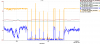
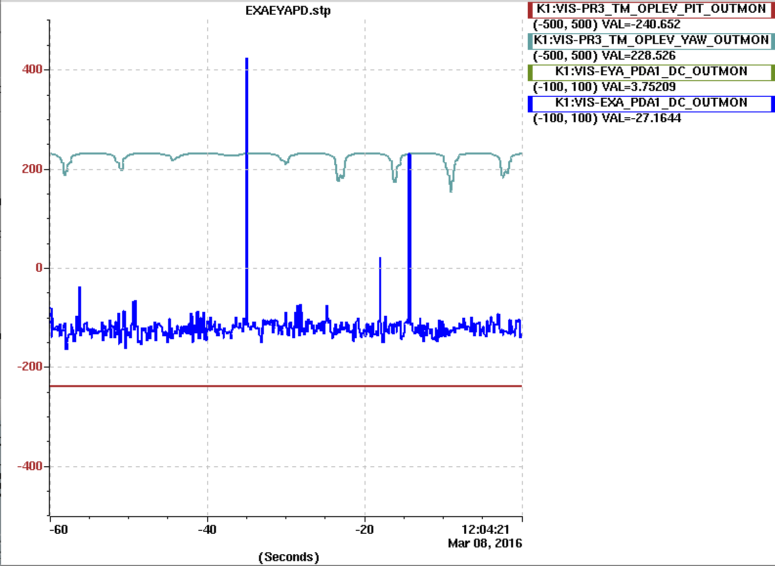
5. At this point, we could see that the beam is constantly hitting the DC PD at EXA (see EXA2.png; as you can see, EXA_PDA1 output is zero when IMC is unlocked).
6. Covered the gap between the PR2-PR3 duct and PR3 chamber to settle down the PR3 motion more.
7. Checked the beam at EXA. At this point, we could'nt see the beam with an IR card. The signal from EXA_PDA1 showed ~50 counts with 70 dB gain setting, and it correspond to ~40 nW. No wonder we could't see the beam.
8. Swept PR3 randomly and find a larger peak when PR3 is tilted ~ -100 urad in pitch. We could see the bright beam at EXA with an IR card.
9. Turned the gain down to 40 dB, so that it won't saturate. EXA_PDA1 showed ~8000 counts at peak (almost saturation), and it correspond to ~0.2 mW. This seems too low considering ~250 mW output from PSL. The aperture of PD (Thorlabs PDA100A) is 9.8 mm dia and the designed beam size at ETMX is 79.3 mm dia. So, PD should receive ~20 % of the beam when centered.
10. Re-centered the PR3 oplev QPD.
Photos:
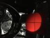
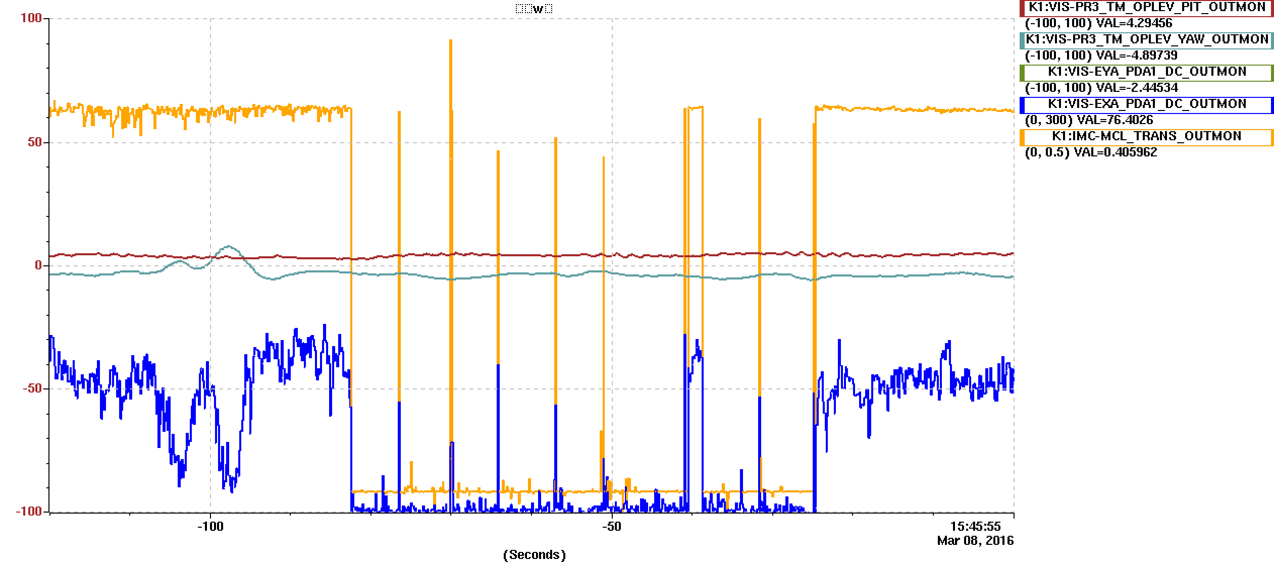
The beam at EXA is attached (EXAbeamshape.jpg; thanks Hasegawa-kun). It clearly show the circular shape, which come from the GV window aperture
The beam around BS (input, transmission, reflection) is also attached (BSIXAbeamshape.pdf; thanks Kataoka-kun). The input beam looks nice, but the upper part of the transmission is clipped, and the upper part of the reflection is clipped by the earth quake stop.
Next:
We are not fully convinced yet that the beam at EXA we found is the direct beam from PR3. So, we have to check the beam more at EXA.
1. Check beam motion at EXA with respect to PR3.
2. Pull the EXA DC PD.
3. Instal ETMX transmission camera.
4. Align ETMX with picomotors so that the beam will return to the BS.
5. Close ETMX chamber and evacutate
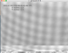
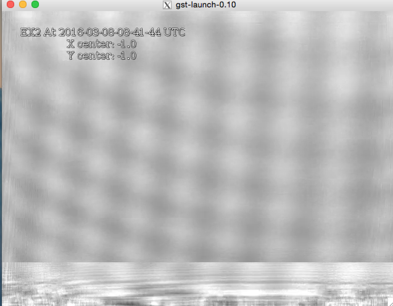
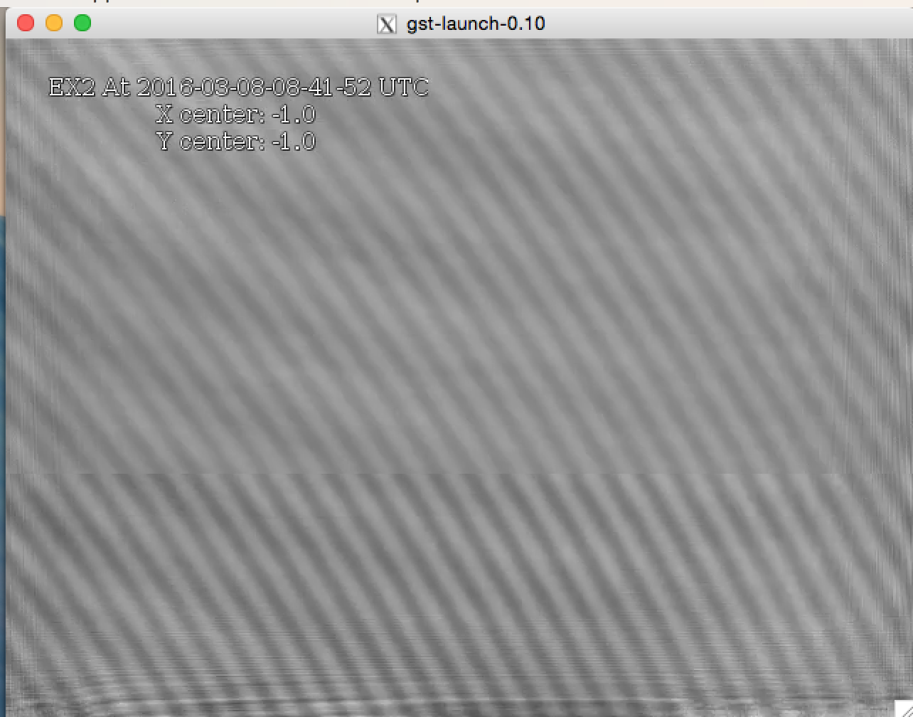
Beam reached to EX was seen by CAM-EX2 (the second end camera, newly prepared). Images are attached. CAM-EX2 was brought into the EXA chamber to see the beam. This camera will be fixed to the EXA_TRANS viewport tomorrow. Interference patterns are seen, likely coming from the clipping effect by the gate valve (between the arm tube and EXA chamber) and the camera window itself.
[Ohishi, Michimura]
EX2 camera at the EXA end viewport. This camera now sees the ETMX transmitted beam. Note that the beam is too large compared with the camera size.
Since the holder of this camera interefere with the vacuum works at EXA, Kimura-san et al. will remove this and set it again tommorow.