Uraguchi, Simon, K. Tanaka, Akutsu, Kokeyama (Enomoto remotely) in the afternoon
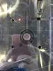
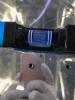
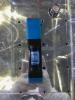
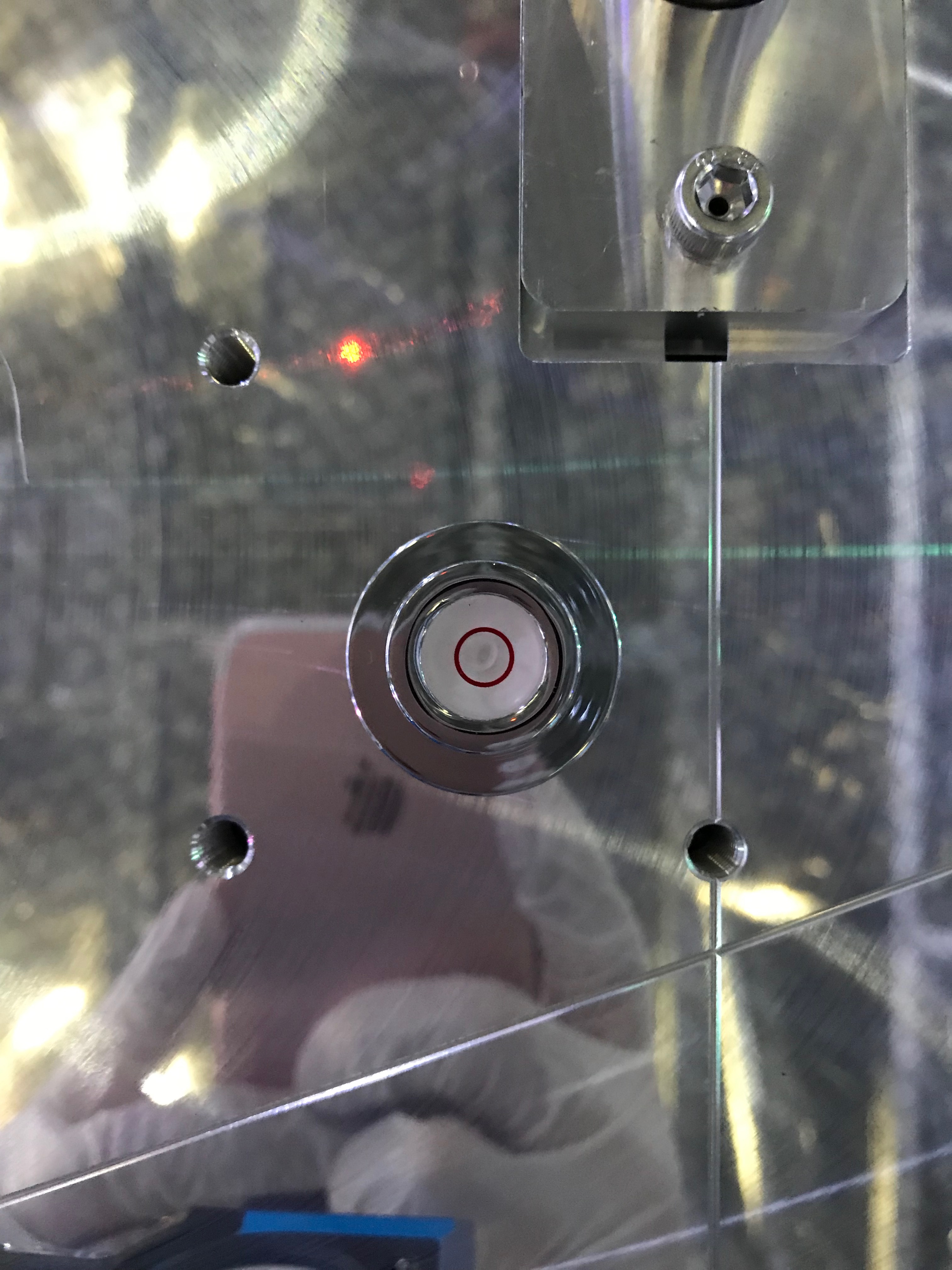
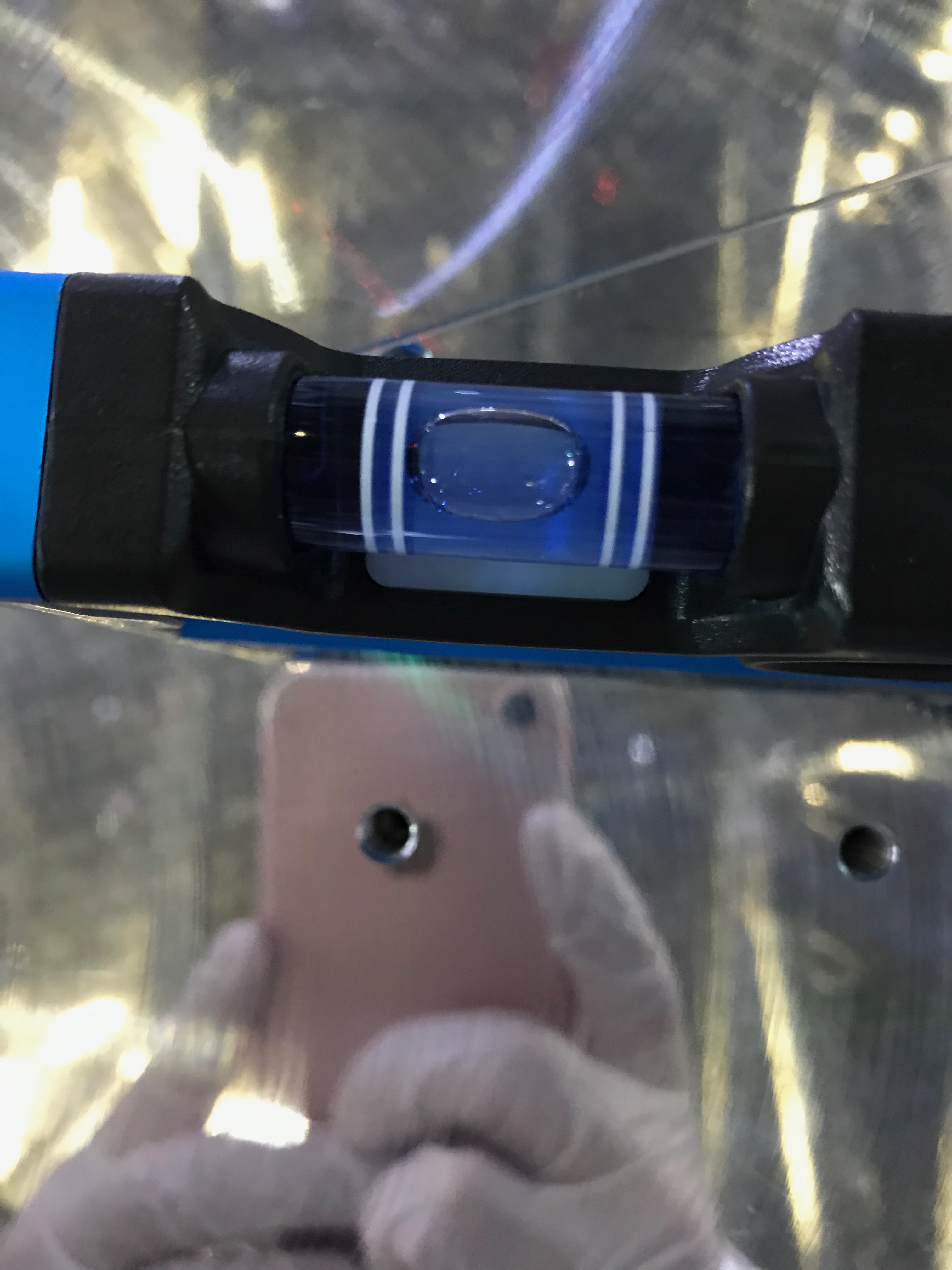
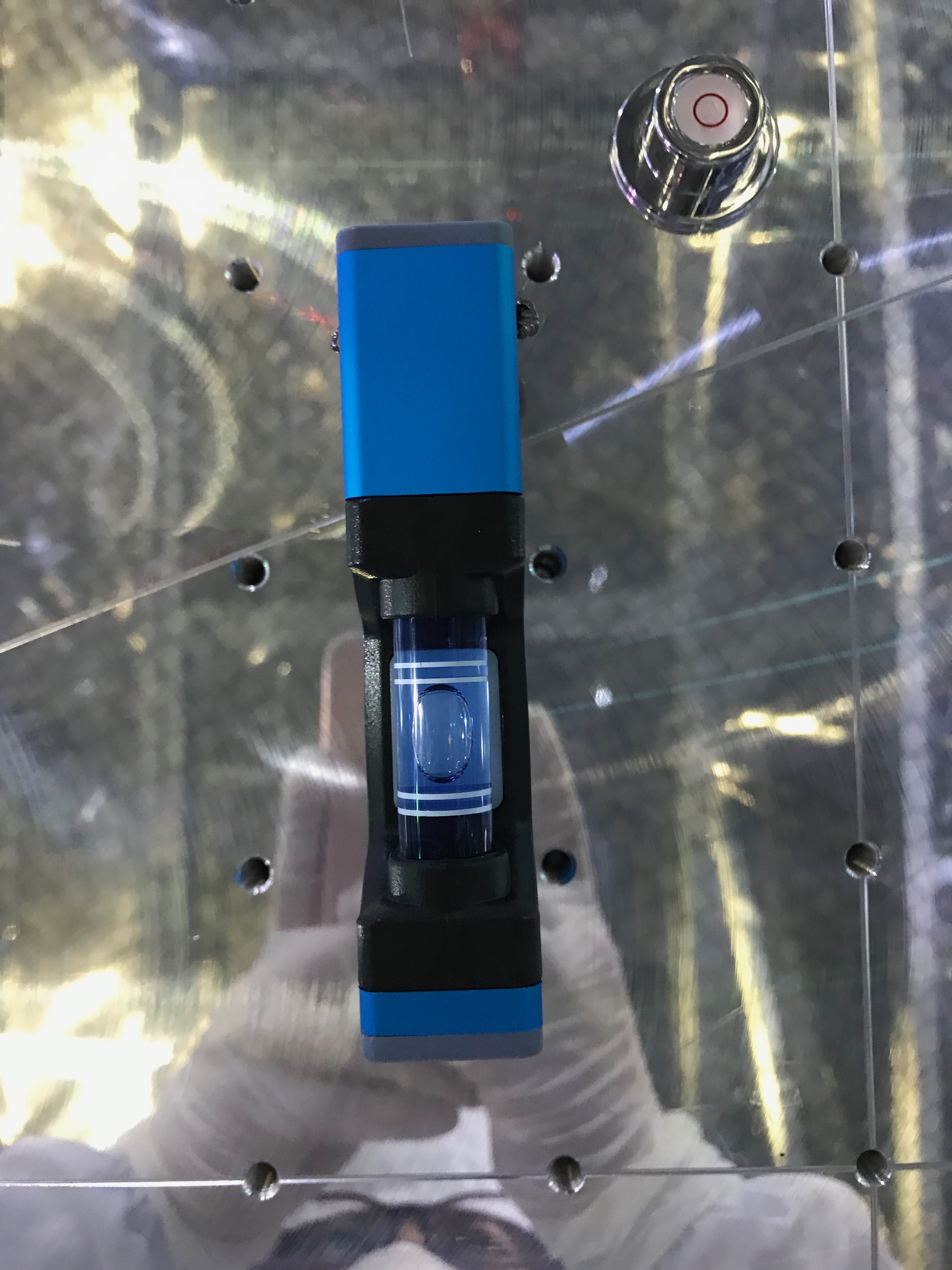
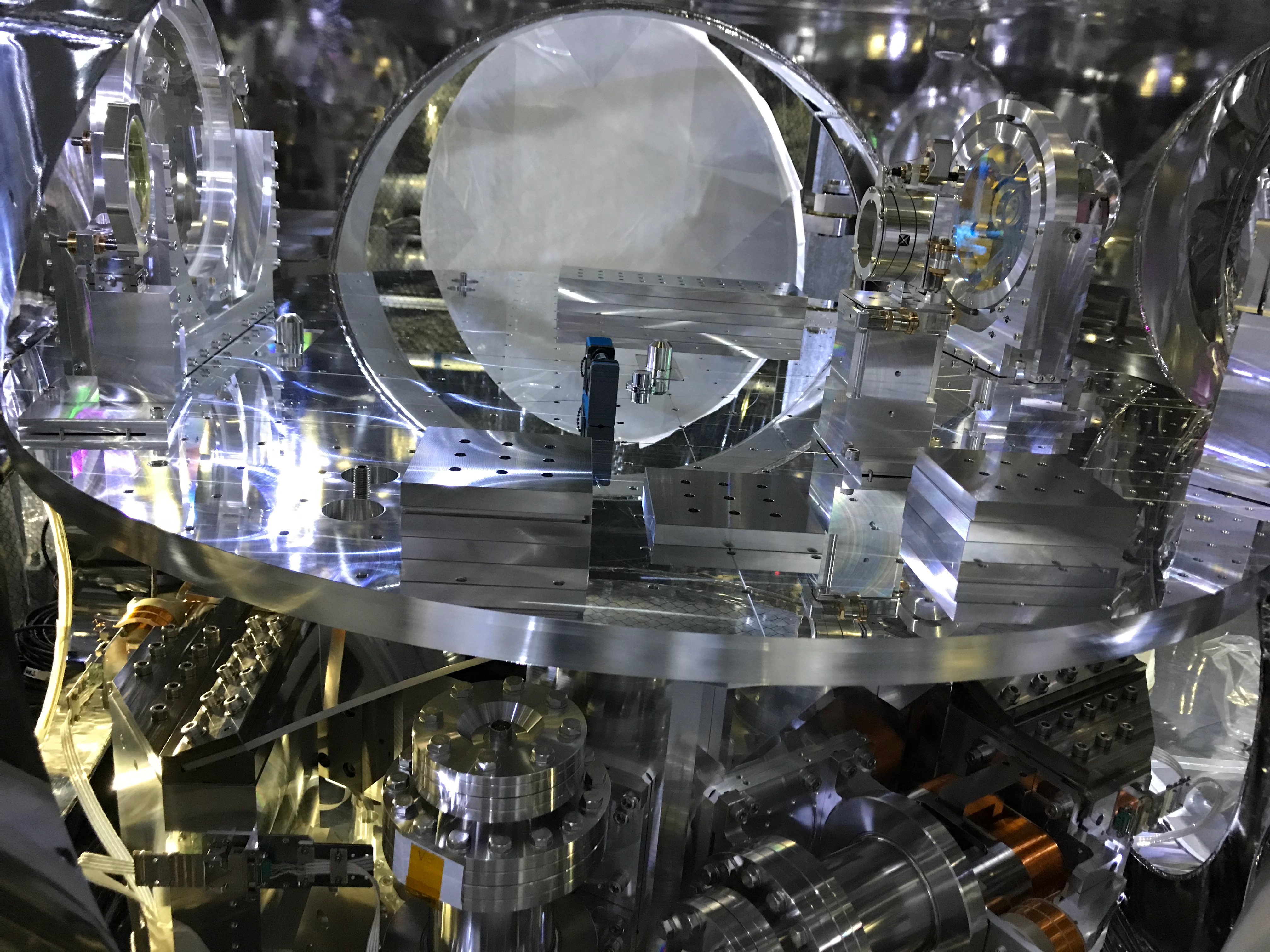
- Uraguchi-san put required (tuned at Mitaka) ballast masses+ dummy masses (Fig 4) on the BRT optical table by referring some photos taken at the trials in Mitaka, and released the TMS-VIS. Surprisingly, it balanced at very nice alignment in terms of leveling. Fig 1 was by the circular leveler, Fig 2 and Fig 3 were by a blue water leveler but facing orthogonal directions.
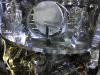
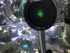
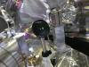
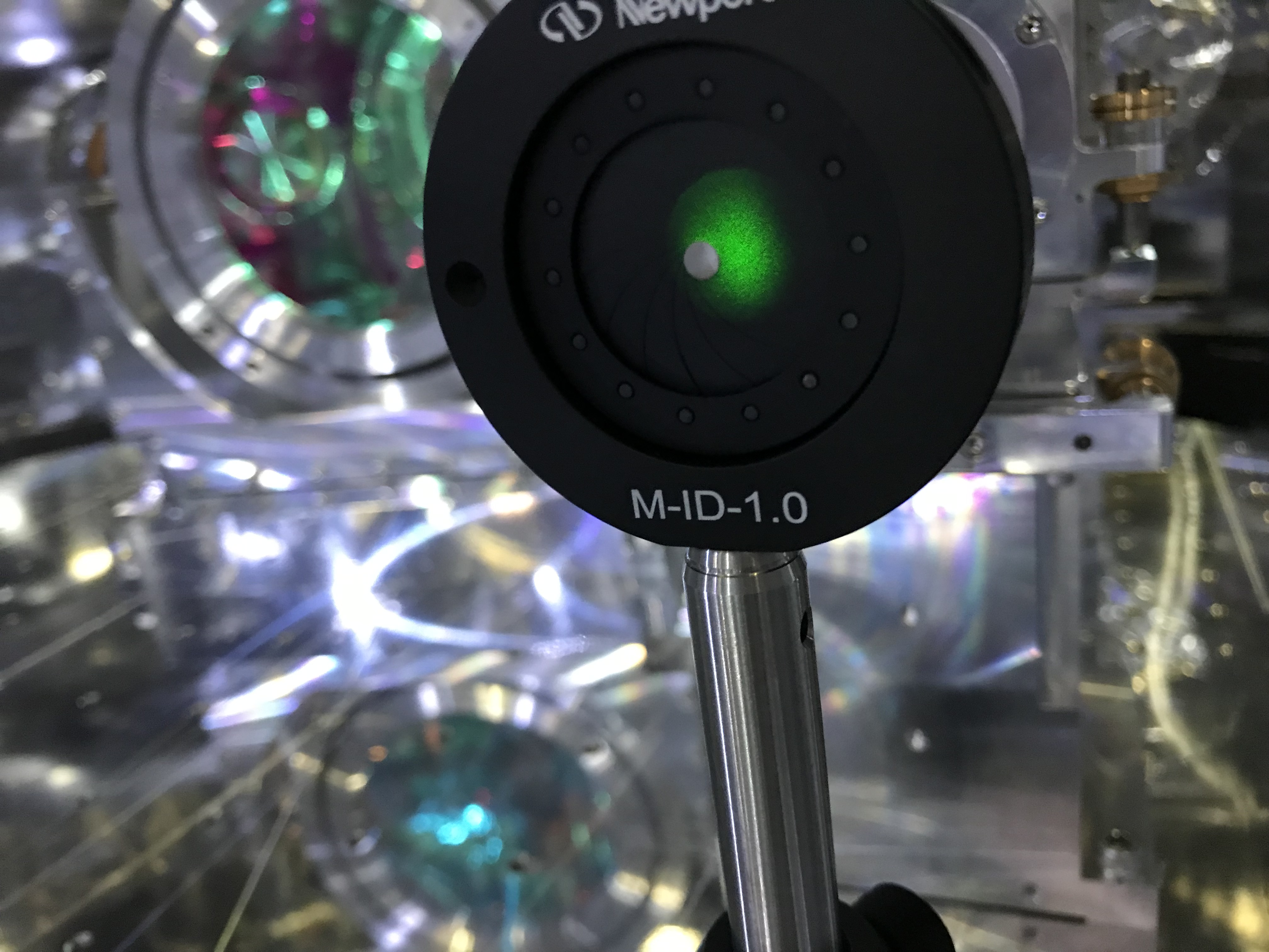
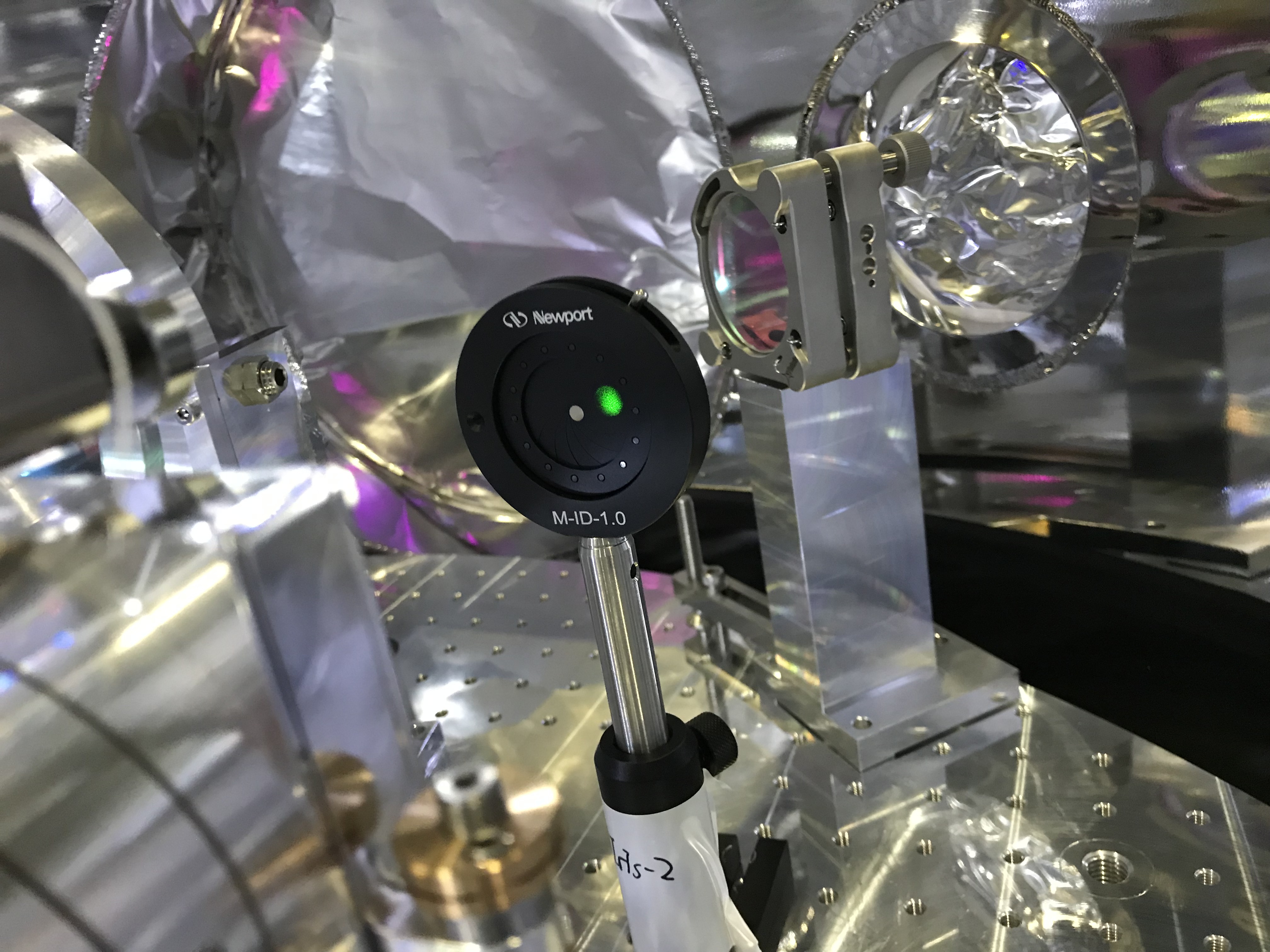
- After removing an aluminum cover shutting the beam tube between the EYC and EYT chambers (an pendulum valve is there), we saw green spots in the BRT. By roughly setting diaphrams at several locations, we identified where the spots were (FIg 5 and 6; I asked Enomoto-kun to somewhat swing SR2 so that the spots came about the center of an aperture-ish area (made-probably-by the 3-km tubet or a viewport window at the pendulum valve or someting). After several handy alignment trials, I estimated the BRT optical table should be rotated a little. As a reference, the beam spots at TMSX were found at 6455 and 7330.
- At the same time, we cabled in the vacuum chamber, and connected the cables to the connectors at the flanges of the EYT chamber.
- At the same time, we cabled in the clean booth after the works reported in 9116. And connected them via flipper-adapters at the flanges of the EYT chamber. Ok, all the cabling have been done.
- Kokeyama-san helped to check the signal outputs from the six LVDTs and six geophones; (1) the ch assignment would be ok. We checked that by disconnecting cables one by one at the flanges of the EYT chamber. (2) all the geophones seemed ok, as they showed signals to some extent (not yet checked in detail). (3) LVDTs...hmm... seemed having some troubles, but probably-fortunately, the coils themselves seemed ok. For some reasons we disconnetcted those LVDT cables at the flanges of the EYT chamber.
About the LVDT stuffs above, whar we saw were:
-
The output of LVDT-H1 did not change so much when connected/disconnected at the flanges of the EYT chamber in the clean booth; it always showed about 300 counts regardless connected/disconnected. That's bad.

- The LVDT-H1 senosr had, however, output signals when it was connected to the line of LVDT-H3.
- When disconnected all the LVDTs at the flanges, they all had certain amounts of offsets, which were not observed at Mitaka, where the lengths of the cables would be much longer than the cases here... (due to the distance between the clean room and the rack room.) The offset counts were H1: 324 counts, H2: -100, H3: 67, V1: -29, V2: -307, V3: -125. Those numbers came back even after rebooting the LVDT driver.
- Those offsets were gone when the calbes were disconnected at the digital rack side. Hmm... ground loop??
- My curiosity asked Kokeyama-san to disconnect the AC bias to the LVDT driver, then we found the offsets zeroed.
Well, continue the investigation.