Lucia, Koki, Yoshinori,
= ETMY =
-- We found that the pin assignment of F0-GAS coils was WRONG:
-- primary coil wires were connected to 3-8 pins and the actuation coil wires were connected to 1-6 pin. (The design was opposite, 1-6 pin for the primary coil, 2-7pin for the secondary coil, 3-8pin for the actuation.)
-- After revising the pin assignments, we could actuate the F0-GAS properly.
-- We then roulghly tuned the gain and the phase of the LVDT board. The calibration factor and the plot will be added.
-- We put the top-flange on the chamber.
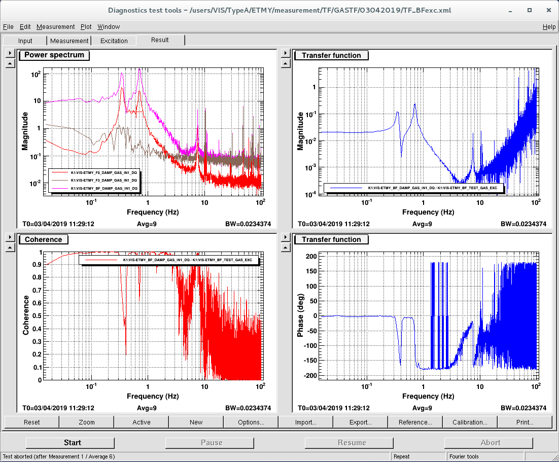
-- Afetr coming back to the control room, we measured the mechancial transfer functions. This result will be also added.
[Lucia, Yoshinori,Fabian]
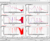
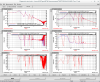
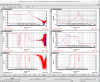
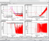
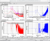
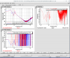
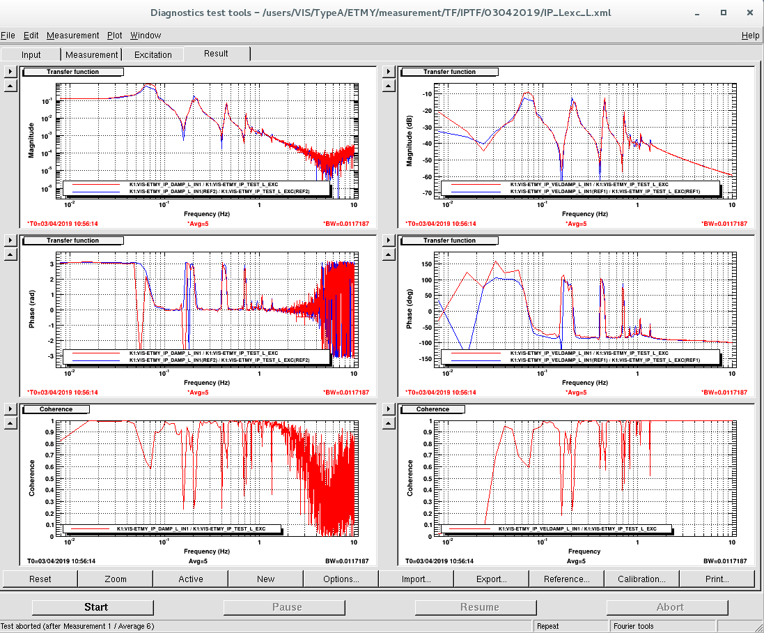
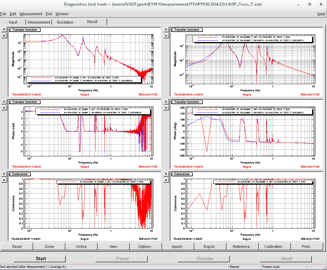
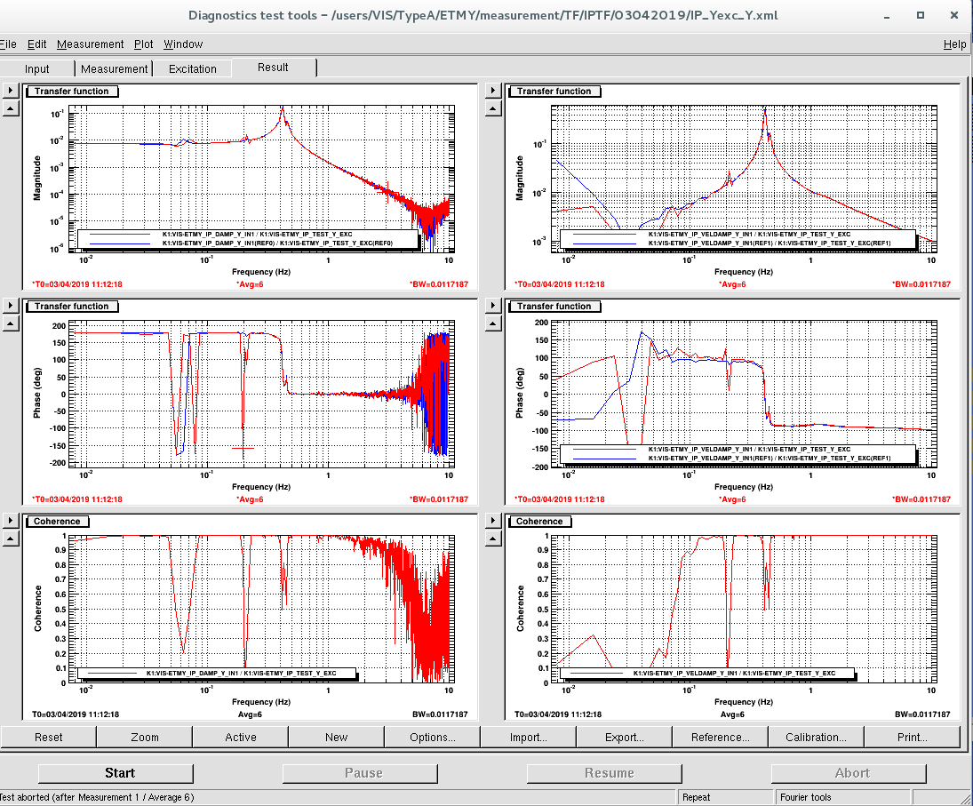
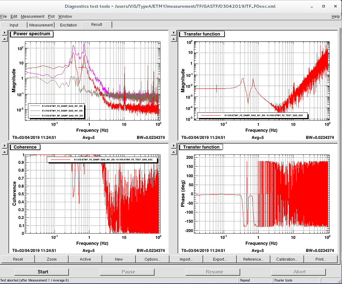
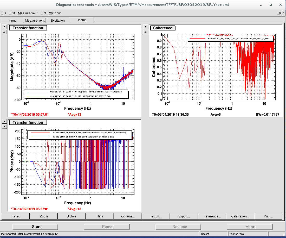
After the recovery of the F0 GAS actuation coil and LVDT we measured the TFs for IP, GAS filters (F0, BF) and BF_Y and we compared them with the old one performed from March.
Now the suspension looks healty!
The plots attached below show the measurements.
-
We found the wrong pin assignment by checking the resistance and inductance of the coils.
- Resistances were measured with a handy digital multimeter, while inductances were measured with an LCR meter borrowed from the AEL tools.
- Comparing the ETMY's measured results to ones in other Type-A suspension (e.g. ITMX), the 1-6 pin coil and the 3-8 pin coil of the ETMY seemed to have swapped parameters.
- Ref. JGW-T1909839: Continuity check and resistance measurement at Type-A installation
| Pins | Resistance [Ohm] | Inductance [mH] @ 100 Hz | |
|---|---|---|---|
| ETMY | 1-6 | 126.8 +/- 0.05 | 103.1 +/- 0.05 |
| 2-7 | 77.1 +/- 0.05 | 10.3 +/- 0.05 | |
| 3-8 | 210.4 +/- 0.1 | 47.0 +/- 0.05 | |
| cf. ITMX | 1-6 | 204.6 | 47.8 +/- 0.05 |
| 2-7 | 79.8 | 10.6 +/- 0.05 | |
| 3-8 | 114.0 | 124.7 +/- 0.01 |
-
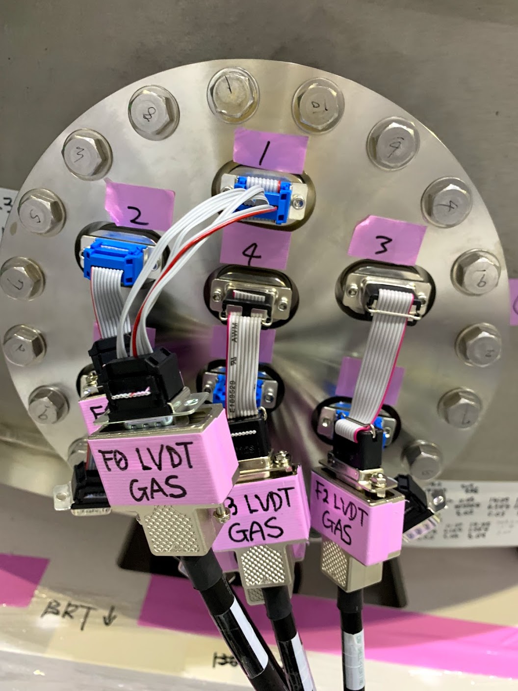
As a workaround, we made a dedicated flipper cable to cancel the swapped pin assignment.
- This special flipper cable is implemented on the output port of the feedthrough as a replacement for the normal flipper cable (see the photo below).
-
-
In addition to the LVDT re-calibration, we also checked that the DC voltage applied to the actuator coil could make a displacement in the F0 GAS keystone with this flipper cable
- Details of the DC voltage injection: klog #8545