With help of Yokozawa-san,
= PRM =
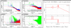
-- IM-tilt check was done; after the one-flag removal, the PRM mirror became tilted in positive PIT and the oplev spot was off from the QPD (fig1). The IM tilt was compensated by the picomotor so that the oplev spot came at the good position which was recorded in ALL_OPLEVS.adl, i.e, PIT~ 150 urad, YAW~ -10urad.
-- After this tilt tuning, it was found that the IM-OSEM-(V1)/V2/V3 signals became saturated. also the OSEM-H1 flag became at close position at its OSEM-body. The options to avoid this situation would be to set the BF-GAS position lower, or to do OSEM-body / plate adjustment.
-- It also looked all the masses were freely suspended (visually).
-- This is going to be checked more concretely by transfer function measurement.
-- After this check, a large offsets like -8000 to K1:VIS-PRM_IM_OPTICALIGN_Y_OFFSET, was injected with ramp time of 60 ~ 120 sec, for a check. Then found that:
-- If the ramp time was like 60 sec for ~7000 to optic_align, no resonance was excited. (I did not try this many times just I have tried 120s and 60s here)
-- even if a large offsets like -8000 was injected, TM was freely suspended, I could not find any touching / hitting part around TM-stage. It was true that some of the horizontal IM-flags looked close to the body though.
-- Somehow I could not center the beam spot on the PSD. (At first I found I was pushing IM to opposite yaw-direction, but even when I pushed IM to apropriate direction, it did not seemed to be centered. ) This wil be checked with experts on next monday.
-- remaining work for PRM:
-- PRM: check the large offset to IM is acceptable and investigate good (better) ramp time for this / measure TM-satge transfer functions with new actuation matrix / release bread board
-- IM-flag position in the misalignment condition is to be checked again.
-- (Do OSEM position alinment again?)
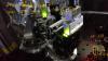
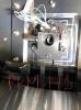
-- photos: https://photos.app.goo.gl/FUKNN37rHJUNWMg56
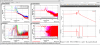
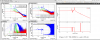
Concerning the TMstage-excited transfer functions:
-- The attachments show the measured (mechanical) transfer functions. They were not so terrible compared to an expectation. This seems a good news.
-- The resonances at 0.11Hz and 0.16Hz of TM-Yaw excited one are the whole chain torsion modes. not sure why they were in the transfer function now.
-- polaity of actuators will be revised.
[Ge, Kokeyama]
We looked at the PRM-PSD to align the PRM-reflected light to hit the beam dump in IFI again. Frist of all steering mirror for PSD was loose at the mount (now fixed), so there is a possibility the PSD setup slightly moved.
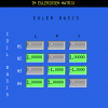
Since we don't believe the PSD anymore, we opended the 152 flange (+Y side, the camera viewport) of the IFI chamber and check the misaligned beam by an IR viewer and sensor card. The misaligned beam was hitting the rear (-Y side) of the beam dump which is not enough misalignement of PRM, even if we misaligned the PRM with maximum offset, -25000 cts yaw without tripping the analog watchdog. With -25000 cts, the spot was still on the -Y side of the dump and more offeset was necessary, otherwise some part of the spot hit the edges and it shines the beamdump (see, the screensthot). It used be only -6000 cts yaw offset to hit the beam dump. With -8000 cts misalign in yaw, the reflected beam hit the heat sink of the beam dump on -Y side and it strongly sined.
Anyway the 152 flange was closed and put the gigE camera was put back.
After leaving the mine, we tried the same procedure above with gigE camera. This time, the scattered light shined very strongly with -17000 cts yaw offset. Something may be strange on the PRM?
Screenshot1: No beam at all. Exposure 1e6.
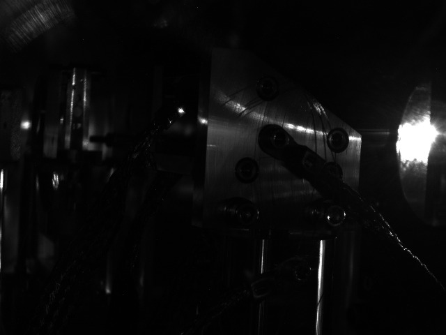
Screenshot2: MC locked, PRM is aligned (IM coil offsets [0, 0]). Exposure 5e5.
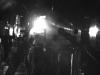
Screenshot3: MC locked, PRM is misaligned (IM coil offsets [-25000, -25000]). Exposure 5e5.


After today's tuning by Fuji-kun et al, the PRM can be misaligned so that the direct reflection from PRM hits the beam dump in the IFI chamber (*). The new offset is [-1500, -9000]. Fuji-kun is still planning to more tuning tomorrow, and the final offset will be reported after that.
* Looking at the IFI camera while misaligning the PRM, we could see the shining spots moving from top (+5000cts in P) to bottom (-8000cts for P) for PIT misalignement and left and right for YAW, of the square edges of the beam dump. We can know that the beam is hitting the beam dump when it looks dark.